Operation of a 2-Stage Bioelectrochemical System for Groundwater Denitrification


Department of Civil Engineering and Architecture, University of Pavia, via Adolfo Ferrata 3, 27100 Pavia, Italy
*
Author to whom correspondence should be addressed.
Water 2019, 11(5), 959; https://doi.org/10.3390/w11050959
Submission received: 26 March 2019
/
Revised: 18 April 2019
/
Accepted: 5 May 2019
/
Published: 8 May 2019
(This article belongs to the Special Issue New Perspective on Groundwater Contamination Treatment: Bioelectrochemical Systems)
Abstract
:Nitrate groundwater contamination is an issue of global concern that has not been satisfactorily and efficiently addressed, yet. In this study, a 2-stage, sequential bioelectrochemical system (BES) was run to perform autotrophic denitrification of synthetic groundwater. The system was run at a 75.6 mgNO3−-N L−1NCC d−1 nitrate loading rate, achieving almost complete removal of nitrate (>93%) and Total Nitrogen (TN) (>93%). After treatment in the first stage reactor values of effluent nitrate compatible with the EU and USA limits for drinking water (<11.3 and 10 mgNO3−-N L−1, respectively) were achieved. Nitrite and nitrous oxide were observed in the first stage’s effluent, and were then successfully removed in the second stage. The observed nitrate removal rate was 73.4 ± 1.3 gNO3−-N m−3NCC d−1, while the total nitrogen removal rate was 73.1 ± 1.2 gN m−3NCC d−1. Specific energy consumptions of the system were 0.80 ± 0.00 kWh m−3, 18.80 ± 0.94 kWh kgNO3−-N−1 and 18.88 ± 0.95 kWh kgN−1. Combination of two denitrifying BES in series herein described proved to be effective.
1. Introduction
Nitrate-contamination of groundwater is a worldwide-diffused issue; nitrate presence has been detected in groundwater in countries in all continents, regardless of their level of development [1,2,3]. An increase in groundwater nitrate concentration in recent years has been reported [4,5].
The main sources for nitrate in groundwater are anthropogenic, due to intensive use of fertilizers [6], other important sources are represented by leakages from sewage systems, on-site wastewater disposal systems, cattle feedlots, and spread of manure and sludge residuals on agricultural land [7,8,9]; this variety of sources is the main cause of the widespread diffusion of the contamination in different areas of the planet despite different land uses and development levels. In addition, nitrate can naturally occur in groundwater, with background natural concentrations reported to be higher than 3 mgNO3−-N L−1 [10].
Groundwater is used in large part of the world as a drinking water source; thus, the intake of nitrate-contaminated water may lead to several health issues. Nitrate has been identified as toxic [11,12,13]. Infant methemoglobinemia can be caused by the consumption of nitrate: nitrite, microbially reduced from nitrate by intestinal bacteria, can oxidize the hemoglobin-contained iron from the ferrous to the ferric form, obtaining methemoglobin, that cannot bind oxygen and thus may lead to cyanosis and brain anoxia [14]. In addition, its intermediate N-form nitrite has been correlated to carcinogenicity due to the formation of nitrosamine in reactions with secondary and tertiary ammines in acidic environments [11,15]. Another intermediate N-form, nitrous oxide, is a known greenhouse gas (GHG) [16], even though it is reported as being neither toxic nor carcinogenic. Due to the health issues connected to the consumption of nitrate-contaminated drinking water, governments and international organizations have issued strict regulations and guidelines on its presence in drinking water, as shown in Table 1.
Different options for nitrate removal from aqueous solutions have been tested and operated so far [23,24]; amongst all, autotrophic denitrification using bioelectrochemical systems (BES) has shown promising results [25,26].
Other than physicochemical methods, conventional biological denitrification techniques exploit the activity of heterotrophic bacteria, in which organic matter is used both as a carbon source and an electron donor. However, some drawbacks in the groundwater denitrification treatment with heterotrophic processes can be identified: the necessary addition of organic matter, otherwise scarcely present in the medium, to avoid limitations in the process kinetics, and the consequent implementation of post-processing techniques (settling, physical retention, and/or other) to remove the excess biomass accumulated during the process [27]. An alternative is represented by autotrophic denitrification, in which organic matter is not necessary to the process. Autotrophic bacteria, in fact, use inorganic carbon as carbon source (e.g., bicarbonates), and the electron sources required to activate their metabolism are also of inorganic origin (e.g., H2, reduced sulfur, iron or manganese species) [28]. In BESs, electrons are provided by an external source and reach the cathodic chamber through the electrode. Different strategies can be operated to maintain a continuous electron flow: by exploiting a bioanode performing oxidation of organic matter [29], or by an abiotic anode and connection with a potentiostat, to maintain cathodic potential at a specific reductive level [30], or by direct electric current provided by a generator [31].
If autotrophic bacteria are performing denitrification, the desired electron acceptor is not oxygen, but nitrate and other possible intermediate nitrogen forms (nitrite, nitric oxide and nitrous oxide) before the final reduction step to N2 gas [25]; a competition between the different electron acceptors is possible [32]. The presence of intermediate N-forms is not desirable due to the abovementioned reasons. Other than nitrate, nitrite [32,33] and nitrous oxide [34] have been removed via biocathodic autotrophic denitrification from contaminated groundwater.
Different microorganisms were detected on the surface of biocathodes; Proteobacteria have been reported as abundant or dominant in several works [35,36,37]. Recently, Vilar-Sanz et al. [36] reported a monospecific biofilm nitrate reduction; however, the nitrite-reducing Alphaproteobacteria strains were not able to reduce nitrate or nitrous oxide, suggesting that a mixed microbial community is necessary to complete a nitrate denitrification pathway in order to dinitrogen gas.
In a previous study by the authors, a 1-stage denitrifying BES reactor was successfully designed and built to remove nitrate from groundwater [38]. However, the denitrification process was incomplete at nitrate loading rates higher than 33.45 mgNO3−-N L−1NCC d−1, indicated by the appearance of nitrite in the effluent. The aim of the study presented herein is the improvement of the removal capacity of nitrate and intermediate N-forms in a BES denitrification reactor by applying a 2-stage process configuration. Therefore, we present a sequential 2-step BES systems composed by 2 BES in series, to overcome the limitations occurred in the application of a single BES, and achieve full autotrophic denitrification of synthetic groundwater. The performances in terms of denitrification and energy consumption are analyzed and discussed.
2. Materials and Methods
2.1. Experimental Setup
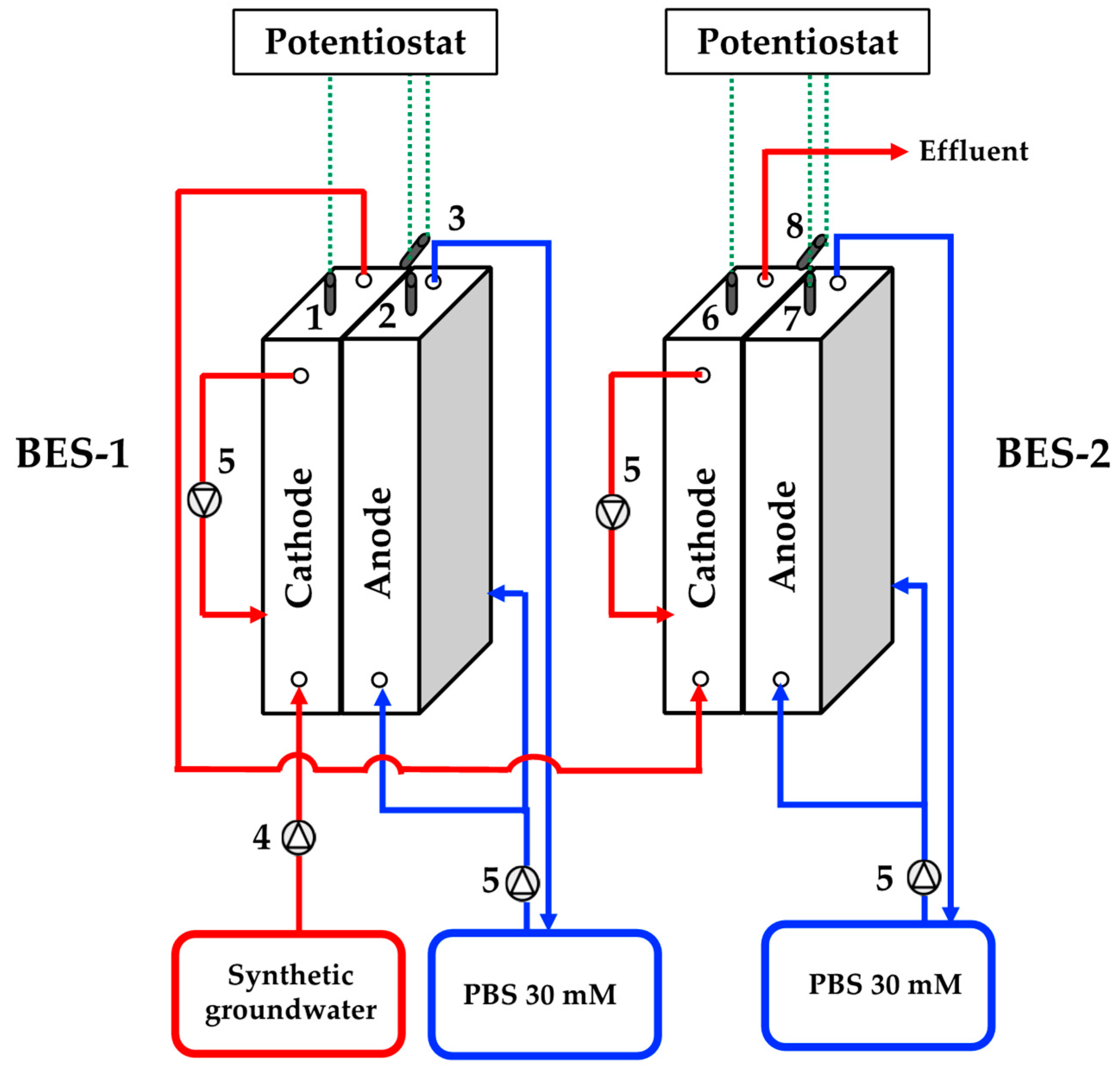
Two dual-chamber BESs (BES-1 and BES-2) based on a previously described scheme [39,40], each consisting of an abiotic anodic chamber and a biotic cathodic chamber on the opposite sides of a methacrylate rectangular frame, were operated and monitored during the study. Cation Exchange Membranes (CEM, CMI-7000, Membranes International Inc., Ringwood, NJ, USA) were used as separators between chambers; CEM was chosen to avoid migration of nitrate and nitrite to the anodic chamber. The cathodic chambers were both filled with granular graphite (model 00514, diameter 1.5–5 mm, EnViro-Cell, Oberursel, Germany), with final free volume of 675 mL net cathodic compartment (NCC) for BES-1 and 520 mL (NCC) for BES-2. A folded stainless steel mesh (40 × 20 cm) was used as electrode in the anodic chamber of BES-1, decreasing its volume to 760 mL net anodic chamber (NAC), while BES-2 anodic chamber was filled with granular graphite obtaining a final free volume of 640 mL (NAC). In order to allow external electrical connection, graphite rod electrodes (250 × 4 mm) were inserted in BES-1’s anodic and cathodic chambers; in the case of BES-2, a stainless steel rod electrode (250 × 5 mm) was inserted in the anodic chamber, while a graphite rod electrode (250 × 4 mm) was inserted respectively in the anodic and cathodic chambers. Ag/AgCl reference electrodes were placed in the cathodic chambers (+0.197 V vs. SHE, Xi’an Yima Opto-Electrical Technology Co., Xi’an, China). A scheme of the system is reported in Figure 1.
Two potentiostats (mod. NEV 3 and NEV 4, Nanoelectra, Alcalá de Henares, Spain) were operated to set applied potentials at the cathodes: in both cases, the potential was set at −0.303 V vs. SHE (−0.5 V vs. Ag/AgCl reference electrode), as already done in a previous work by the authors [38]. Dosage of influents and recirculation were performed using two peristaltic pumps (BT100N, Baoding Shenzhen Precision Pump Co., Shenzen, China), with continuous closed-loop recirculation to achieve well-mixed conditions in the BES. Well-mixed conditions are essential to achieve the necessary contact between the substrate and the biomass [41]. Synthetic groundwater with micronutrients (0.326 g L−1 KNO3, 1.600 g L−1 NaHCO3, 0.003 g L−1 KCl, 2.458 g L−1 Na2HPO4, 1.522 g L−1 NaH2PO4) was fed to the cathodic chambers during the experiments. Phosphate buffer solution (PBS, 30 mM, pH 7), with the following composition: 1.228 g L−1 Na2HPO4, 0.761 g L−1 NaH2PO4 was used as pH-control for the anodic chamber. The value of pH was chosen as a value feasible for groundwater, falling in the ranges previously reported by Bundschuh et al. [42] and Frengstad et al. [43]. The conductivity of the cathodic influent was 4152 ± 567 µS cm−1; Hu et al. [44] reported an electrical conductivity in groundwater between 760 and 6640 µS cm−1; a lower value (1000 µS cm−1 or lower) was reported by Pous and co-workers to negatively affect biocathodic denitrification [45]. No organic matter was supplied to the BES during the experimentation. Both BES-1 and BES-2 were inoculated using the effluent of a parent BES performing cathodic autotrophic denitrification [38]. The biocathode in the parent BES was obtained by switching an anodic biofilm to cathodic conditions, as described by Molognoni et al. [30]; such a procedure based on the bidirectional microbial electron-electrode transfer of ano-cathodophilic biofilms allows the development of a thicker and more diversified biofilm in a shorter period of time compared to conventional inoculation processes [46]. Both the BESs object of this study were connected to a tank containing the effluent of the parent biocathode; once the electrical activity of the BESs was visible (after 2 days), they were disconnected and fed with the synthetic groundwater. After the electrical activity had reached a stability (in a one-month period), the BES were connected in series.
2.2. Operating Conditions
The system was run at the maximum NO3−-N concentration applied in our previous study (45.2 mgNO3−-N L−1) and at a 2 L d−1 flow-rate for a duration of 2 months, thus at a nitrate loading rate (75.6 mgNO3−-N L−1NCC d−1, calculated on the total NCC of the system) higher than the maximum applied in our previous work (67.0 mgNO3−-N L−1NCC d−1) [38]. The hydraulic retention time (HRT) of the entire system was 9.56 h. The HRT of BES-1 was 5.4 h, while that of BES-2 was 4.16 h. Anodic solution was continuously recirculated in closed-loop mode, and substituted when its pH reached a value of 5 (usually every two weeks).
The experiments were performed at ambient temperature (23 °C); groundwater temperature is a highly-variable parameter due to seasonal variations and because of different climates [47], other than being influenced by the depth of the aquifer and by anthropic activities [48,49]. Worldwide groundwater temperature has been reported in a very large range (5–30 °C) [50].
2.3. Analytical Methods and Calculations
Effluents of both cathodic chambers were characterized for NO3−-N, NO2−-N and total nitrogen (TN) concentrations. NO3−-N and TN concentrations were determined by spectrophotometric analysis (HI83224 Wastewater Treatment Photometer, Hanna Instruments, Milan, Italy); NO2−-N concentration by nitrite test kits (HI3873, Hanna Instruments, Milan, Italy). N2O-N concentration was calculated as the difference between TN and other N-forms, NO was not considered in the balance due to its extremely fast reduction kinetics [51]. No effluent gaseous analyses were performed throughout the experiment. Conductivity and pH of influents and effluents were measured daily using a multi-parametric probe (IntelliCALTM probes + HQ40dTM Digital Meter, Hach Lange, Lainate, Italy). Electrical consumption, in terms of current and power, were monitored and logged every minute on both BESs by a potentiostat connected to a PC. Current density (A m−3NCC) and power density (W m−3NCC) for each BES were consequently calculated by respectively dividing the current and the power by the correspondent NCC. Nitrate and TN removals were calculated as difference between influent and effluent concentrations, integrated over treated volume, for each BES. Nitrate and TN removal rates (respectively, gNO3−-N m−3NCC d−1 and gN m−3NCC d−1) were calculated as shown in Equations 1 and 2, as proposed in Molognoni et al. [30]:
where are influent and effluent concentrations of NO3−-N (mgNO3−-N L−1), Q is the flow-rate (L d−1), CTN,in and CTN,out are TN influent and effluent concentrations (mgN L−1), respectively. For the calculation of the removal rates of BES-1 and BES-2, the relative NCC were used. In the case of the sequential system, the NCC was calculated as the sum of the NCCs of BES-1 and BES-2.
The quality ratio (QR) for drinking water was calculated as follows [19]:
where is the concentration of nitrous nitrogen in the effluent; QR should not exceed 1.
Based on observed data, the Specific Energy Consumptions SECV (volumetric, kWh m−3treated), SECN (nitrate specific, kWh kgNO3−-N−1), and SECTN (total nitrogen specific, kWh kgN−1) were computed based on Cecconet et al. [52]:
where P(t) represents the power demand, Vtreated the treated volume, mNO3--Nrem and mTNrem respectively the daily amount of nitrate and total nitrogen removed.
When considering the combined system (BES-1 followed by BES-2), the SEC relative to the system were computed as follows, as proposed in Cecconet et al. [53]:
where SECV,tot is the volume specific SEC of the system (kWh m−3treated), SECN,tot is the nitrate specific SEC of the system (kWh kgNO3−-N−1), SECTN,tot is the total nitrogen specific SEC of the system (kWh kgN−1), P1(t) and P2(t) are the power demand values recorded by the potentiostats connected to BES-1 and BES-2 respectively, mNO3−-Nrem,tot is the mass of NO3−-N removed by the system and mTNrem,tot is the mass of total nitrogen removed by the system. Coulombic efficiency (CE, %) for BES-1, BES-2, and the sequential system was calculated using the method reported in Pous et al. [54].
Unless otherwise stated, the results reported in the following sections are expressed as average (during the whole experimentation) ± standard deviation.
3. Results and Discussion
3.1. Nitrogen Removal
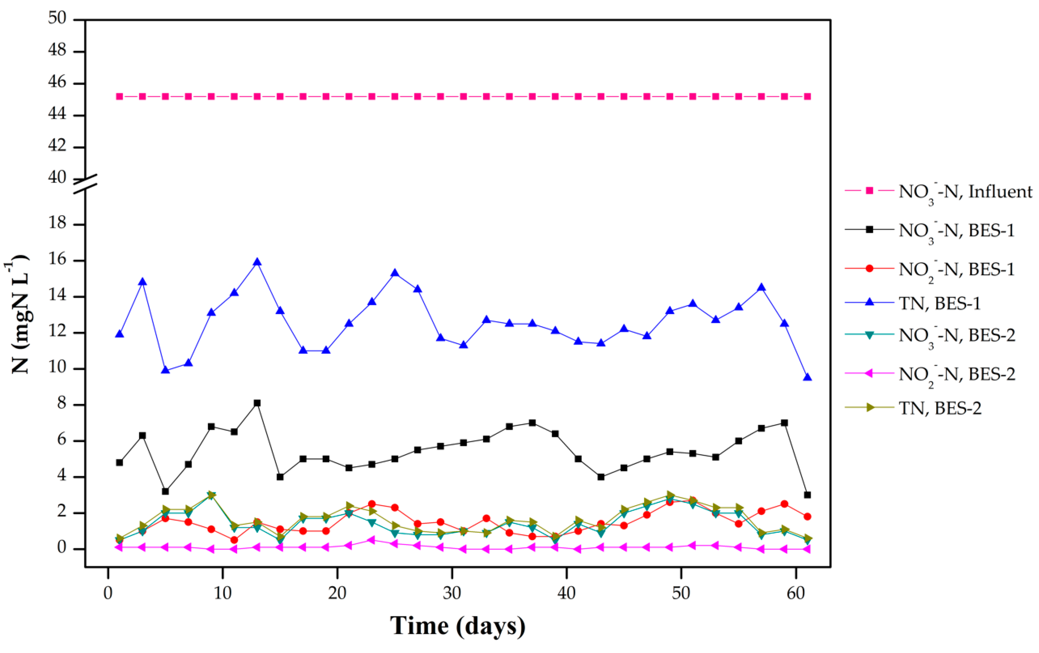
The effluent N-forms of each BES during the whole experimentation are shown in Figure 2; due to the configuration of the sequential treatment, BES-2’s effluent was also the effluent of the system.
BES-1 was able to achieve excellent results in terms of nitrate removal (88 ± 3% throughout the whole experimentation) and obtain a nitrate concentration in the effluent lower than 8.2 mgNO3−-N L−1, thus able to fulfill the nitrate limits imposed by the majority of the regulations reported in Table 1. On the other hand, the nitrite concentration in BES-1 effluent was far higher than the admissible value (1.5 ± 0.6 mgNO2−-N L−1), leading BES-1 to score a 72 ± 3% TN removal. Therefore, the QR relative to the effluent of BES-1 was higher (2.1 ± 0.6) than the admissible value (1.0). These results confirmed that a single biocathodic BES may not be able to achieve full denitrification at relatively high nitrate loads, as previously shown in Cecconet and co-workers [38]. Surprisingly, the majority of non-nitrate TN was originated from nitrous oxide, which concentration was far higher than that of nitrite during the whole experiment, and whose presence was not relevant in our previous experience. Based on those results, a single stage consisting in BES-1 was not sufficient to ensure sufficient quality as prescribed for drinking water production. The addition of a second stage (BES-2) led to the nearly complete removal of nitrite and nitrous oxide (0.1 ± 0.1 mgNO2−-N L−1 and 0.1 ± 0.1 mgN2O-N L−1, respectively), and to a reduction in nitrate concentration (1.4 ± 0.7 mgNO3−-N L−1). It is remarkable that the sequential system was able to constantly maintain the concentration of nitrate and nitrite under the prescribed limits for drinking water production, despite the high nitrate loading rate of the system (75.6 mgNO3−-N L−1NCC d−1); in addition, the system scored a QR value of 0.2 ± 0.1, far below the maximum acceptable value. Even though pH has been claimed as a major player in the biocathodic denitrification process, with optimal values around 7.5 [38,55], in this study no evidence of accumulation of intermediate N-forms due to pH was recorded: BES-2, whose influent pH was far from neutrality (8.6 ± 0.5) due to its correspondence with BES-1 effluent, succeeded in achieving almost a complete removal of nitrite and nitrous oxide during the whole experimentation. No N-forms were detected in the anodic chamber.
The nitrate removal rate of the sequential system during the experimentation was 73.4 ± 1.3 gNO3−-N m−3NCC d−1; those of BES-1 and BES-2 were respectively 117.3 ± 4.1 and 16.3 ± 5.9 gNO3−-N m−3NCC d−1. The limitation in the nitrate removal rate scored by BES-2 can be attributed to the fact that the majority of the nitrate was removed in the first stage. Contrary, BES-2 was active mainly in the removal of nitrite and nitrous oxide; therefore, the difference of TN removal rates between BES-1 and BES-2 was lower (95.7 ± 5.1 and 43.6 ± 7.9 gN m−3NCC d−1, respectively). The sequential system scored a 73.1 ± 1.2 gN m−3NCC d−1 TN removal rate, very close to the nitrate removal rate, suggesting a complete autotrophic denitrification.
3.2. Electric Performances and Energy Consumption
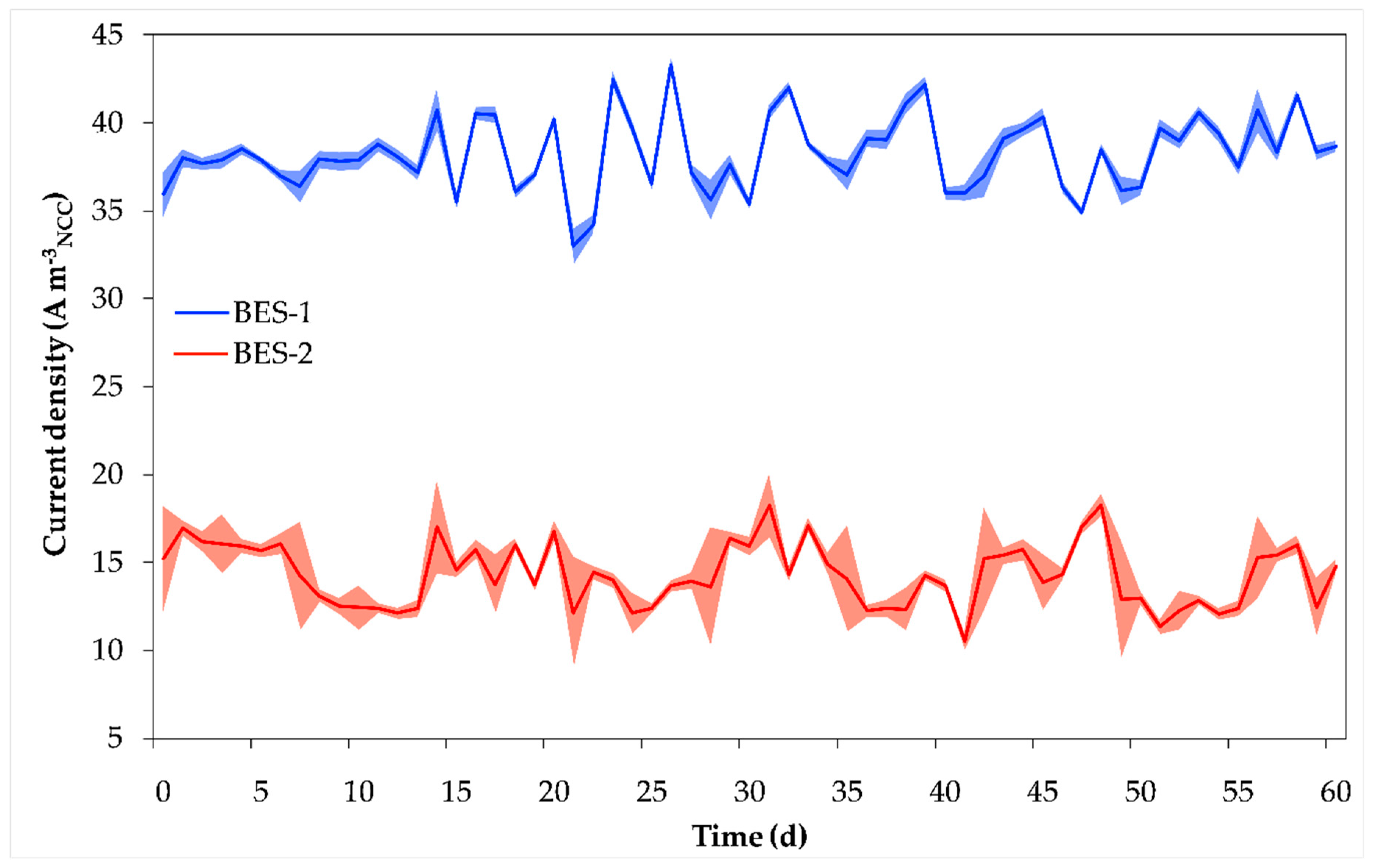
Current and power were recorded during the whole experimentation by the connected potentiostats. In the case of current density (Figure 3), BES-1 reached higher values than BES-2 (37.7 ± 0.8 A m−3NCC and 14.0 ± 2.1 A m−3NCC respectively): this may be explained by the fact that BES-1 was working in a fully-operative mode, while BES-2’s action was limited to a polishing step of BES-1 effluent, and consequently working at a lower nitrate load than BES-1. Higher standard deviations in BES-2 current density may be attributed to the variability of the effluent of BES-1, that instead was receiving an influent with constant nitrate concentration. BES-1 scored a 57 ± 4% CE, lower than that of BES-2 (90 ± 5%); the sequential system obtained a 61 ± 5% CE.
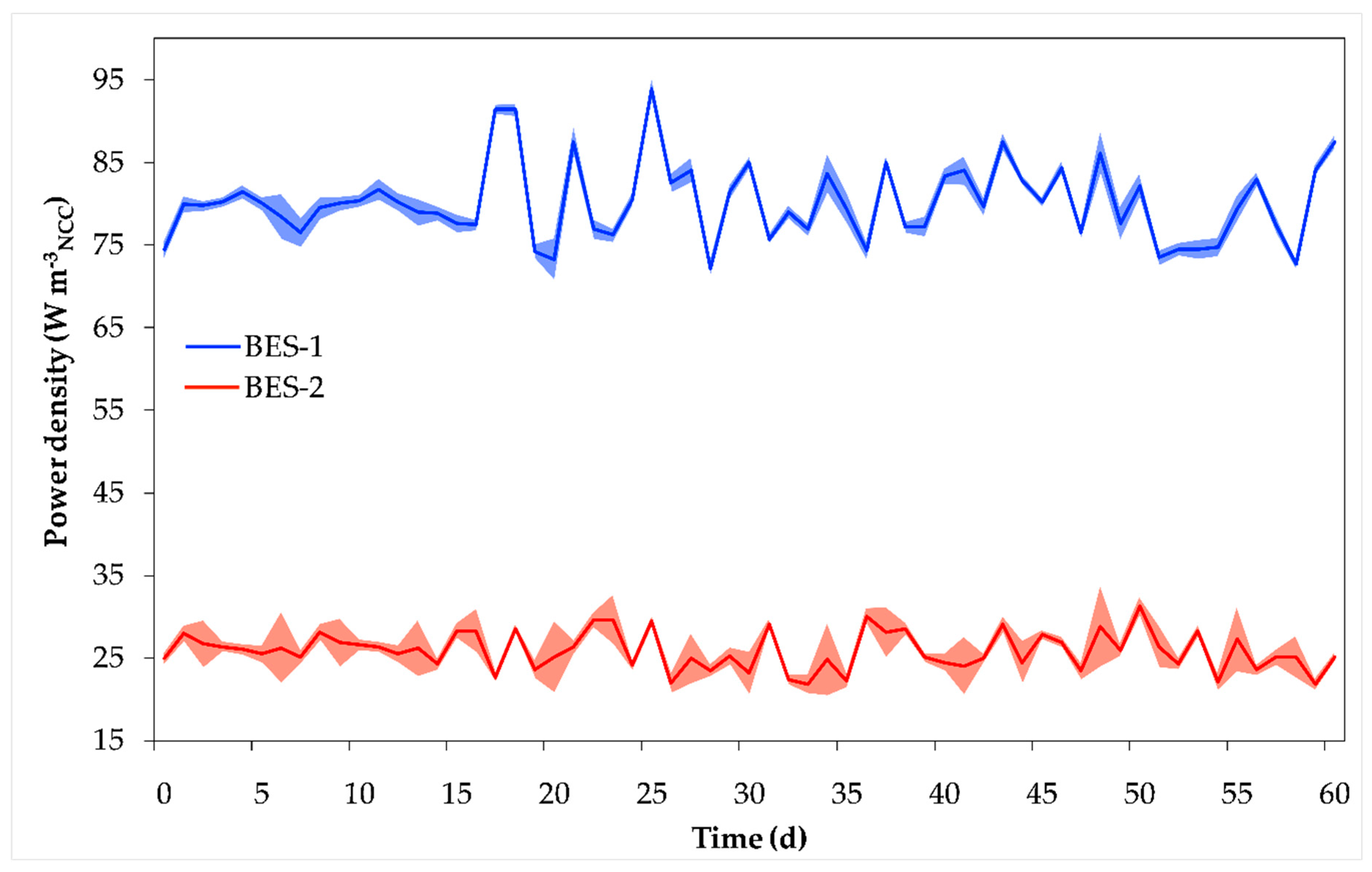
The power density (Figure 4) values followed the same scheme of the current density; higher power demands were recorded by BES-1 rather than by BES-2 (26.4 ± 2.3 W m−3NCC and 26.4 ± 2.3 W m−3NCC respectively); this may confirm that BES-2 was not working at full load.
The SECs of each single stage and of the whole system were calculated, and are reported in Table 2 and Table 3. Interestingly, the mean SECN value of BES-2 was higher than that of BES-1 even though its power density was lower: this can be explained by the lower mass of nitrate removed by BES-2 due to the majority of the denitrification process (in particular the nitrate-nitrite step) being carried out by BES-1. This is another hint that the system may work at a higher nitrate load to fully profit from the presence of BES-2.
The SECN,tot of the sequential system (18.80 ± 0.94 kWh kgNO3−-N−1) was far lower than other values reported in literature for single-stage denitrifying BESs, that recorded SECN values of 89 kWh kgNO3−-N−1 [26] and 68 kWh kgNO3−-N−1 [56], but higher than that reported (3.17 kWh kgNO3−-N−1) in our previous work [38]; it has been reported that in potentiostatically-controlled biocathodes the energy consumption is strongly dependent on the amount of terminal electron acceptors (TEA) available [38,52]: thus, the sequential system was operated at a higher nitrate loading rate than our previous work [38], and this, in combination with the presence of 2 BESs, may explain the higher energy consumption. On the other hand, it showed a higher energy consumption than that reported in the sequential denitrifying BES described by Cecconet et al. [53] (12.59 kWh kgNO3−-N−1): SECN was shown to decrease at the increase of nitrate loading rate, with the system achieving lower specific energy consumption at the maximum nitrate loading rate of 301.3 gNO3−-N m−3NCC d−1; the lower nitrate loading rate reported in this work (75.6 gNO3−-N m−3NCC d−1) may be the cause of the higher energy consumption compared to the other reported sequential system [53].
Using SECN and SECV it is possible to compare the energy consumption of the sequential system to that of other non-BES technologies: the system showed SECN in the range reported for electrodialysis by Ortiz et al. [57] (49.5–10.1 kWh kgNO3−-N−1), and SECV slightly lower than the minimum reported (0.92 kWh m−3) by the same authors. Compared to SECV reported for reverse osmosis (1.03–2.09 kWh m−3) by Twomey and coworkers [58], the system showed a lower value (0.80 kWh m−3).
3.3. Technological Perspectives
The technology herein presented appears to be effective for nitrogen forms removal from groundwater, compatibly with the stricter concentration limits prescribed by the EU drinking water legislation. The system was tested in laboratory scale achieving satisfactory results, however, with some adaptations groundwater treatment with BES technology could also become a feasible option for in situ denitrification. Different strategies have been reported by other researchers for in situ treatment of different contamination plumes, for example, the treatment of hydrocarbon-contaminated aquifers, such as the insertion of permeable barriers in confined or unconfined aquifers to provide treatment exploiting the natural flow of the water [62]. Cecconet et al. [52] recently analyzed the estimated energy demands related to the application of similar systems of controlled biocathodic denitrification in ex situ on-site and in situ modes. They assessed that energy requirements for BES power supply outcompeted all the other energy expenditures under the various scenarios considered, with specific theoretical energy consumption (based on mass of NO3-N removed) of 19 and 10 kWh kgNO3-N−1, respectively for in situ and ex situ on-site treatments (the latter not including water pumping to the surface for treatment), very similar to the experimental values determined herein.
Pumping extraction of groundwater for on-site treatment could however have a greater impact on energy consumption, depending on water table depth and nitrates concentration, increasing potential treatment costs. This could however make sense if treatment is done just prior to the point of supply of a distribution system, without the need for groundwater re-injection.
Very similar systems could also be applied to solve contamination problems related to the presence of different harmful contaminants at the same time (e.g., arsenic) in aquifers, potentially achieving simultaneous removal of both pollutants; BES have already proved to be able to remove a wide variety of contaminants from groundwater: besides nitrate, sulfate, perchlorate, aromatic hydrocarbons and metal ions have also been removed or recovered through BES so far [63,64].
Considering the many pollutants that affect groundwater quality nowadays due to anthropogenic impact, an interesting perspective would be to evaluate lab-scale the efficiency of BES systems not only treating a single compound at a time (like often reported in literature), but processing cocktails of contaminants, in order to increase the feasibility and the appeal of BES systems for real scale application despite the high investment costs.
Pous et al. [65] reported that nitrate and nitrite reduction happened at different potentials; the operation of the sequential system with different set potentials in the different steps may constitute an evolution of the BES-based denitrification described in this study; a similar approach could be applied to other contaminants in groundwater.
4. Conclusions
Autotrophic bioelectrochemical nitrate removal systems could constitute an efficient methodology for denitrification of drinking water groundwater supplies. This study showed that a 2-stage BES could efficiently treat contaminated groundwater to comply with drinking water regulation requirements. Although this has been done at laboratory scale so far, it is not unrealistic to imagine such a system being scaled-up for field use, to accommodate the large flows that are required to process the volumes needed by water supply distribution systems.
As described in this paper, an autotrophic bioelectrochemical nitrate-removal system was built and operated, treating the 2 L d−1 of nitrate-contaminated synthetic groundwater with nitrate concentration of 45.2 mgNO3−-N L−1. The 2-stage nitrate and nitrite removal efficiency was close to 100%, with specific energy consumptions (SECV,tot, SECN,tot and SECTN,tot) of 0.80 ± 0.00 kWh m−3, 18.80 ± 0.94 kWh kgNO3−-N−1 and 18.88 ± 0.95 kWh kgN−1. The average nitrate and TN removal rate scored by the system were 73.4 ± 1.3 gNO3−-N m−3NCC d−1 and 73.1 ± 1.0 gN m−3NCC d−1. The system specific energy consumption was lower than in other single-stage BESs reported in literature and close or lower to values reported for nitrate removal using reverse osmosis and electrodialysis.
Author Contributions
A.C. and D.C. conceptualized the experiment; S.B. performed the experiment; S.B. and D.C. processed the data; A.C. and D.C. wrote the paper; S.B. reviewed the paper. All the authors contributed substantially to the work reported.
Funding
This research received no external funding.
Conflicts of Interest
The authors declare no conflict of interest.
References
- Nisi, B.; Vaselli, O.; Delgado Huertas, A.; Tassi, F. Dissolved nitrates in the groundwater of the Cecina Plain (Tuscany, Central-Western Italy): Clues from the isotopic signature of NO3−. Appl. Geochem. 2013, 34, 38–52. [Google Scholar] [CrossRef]
- Re, V. Incorporating the social dimension into hydrogeochemical investigations for rural development: The Bir Al-Nas approach for socio-hydrogeology. Hydrogeol. J. 2015, 23, 1293–1304. [Google Scholar] [CrossRef]
- Wheeler, D.C.; Nolan, B.T.; Flory, A.R.; DellaValle, C.T.; Ward, M.H. Modeling groundwater nitrate concentrations in private wells in Iowa. Sci. Total Environ. 2015, 536, 481–488. [Google Scholar] [CrossRef] [PubMed]
- Niu, B.; Loa’iciga, H.A.; Wang, Z.; Zhan, F.B.; Hong, S. Twenty years of global groundwater research: A Science Citation Index Expanded-based bibliometric survey (1993–2012). J. Hydrol. 2014, 519, 966–975. [Google Scholar] [CrossRef]
- Zhang, S.; Mao, G.; Crittenden, J.; Liu, X.; Du, H. Groundwater remediation from the past to the future: A bibliometric analysis. Water Res. 2017, 119, 114–125. [Google Scholar] [CrossRef]
- Bouchard, D.C.; Williams, M.K.; Surampalli, R.Y. Nitrate contamination of groundwater: Sources and potential health effects. J. Am. Water Works Assoc. 1992, 84, 85–90. [Google Scholar] [CrossRef]
- Wakida, F.T.; Lerner, D.N. Non-agricultural sources of groundwater nitrate: A review and case study. Water Res. 2005, 39, 3–16. [Google Scholar] [CrossRef] [PubMed]
- Capodaglio, A.G.; Muraca, A.; Becchi, G. Accounting for water quality effects of future urbanization: Diffuse pollution loads estimates and control in Mantua’s Lakes (Italy). Water Sci. Technol. 2003, 47, 291–298. [Google Scholar] [CrossRef]
- Ogrinc, N.; Tamše, S.; Zavadlav, S.; Vrzel, J.; Jin, L. Evaluation of geochemical processes and nitrate pollution sources at the Ljubljansko polje aquifer (Slovenia): A stable isotope perspective. Sci. Total Environ. 2019, 646, 1588–1600. [Google Scholar] [CrossRef]
- Menció, A.; Mas-Pla, J.; Otero, N.; Regàs, O.; Boy-Roura, M.; Puig, R.; Bach, J.; Domènech, C.; Zamorano, M.; Brusi, D.; et al. Nitrate pollution of groundwater; all right…, but nothing else? Sci. Total Environ. 2016, 539, 241–251. [Google Scholar] [CrossRef] [Green Version]
- Pawełczyk, A. Assessment of health hazard associated with nitrogen compounds in water. Water Sci. Technol. 2012, 66, 666–672. [Google Scholar] [CrossRef] [PubMed]
- Lohumi, N.; Gosain, S.; Jain, A.; Gupta, V.K.; Verma, K.K. Determination of nitrate in environmental water samples by conversion into nitrophenols and solid phase extraction-spectrophotometry, liquid chromatography or gas chromatography-mass spectrometry. Anal. Chim. Acta 2004, 505, 231–237. [Google Scholar] [CrossRef]
- Fewtrell, L. Drinking-water nitrate, methemoglobinemia, and global burden of disease: A discussion. Environ. Health Perspect. 2004, 112, 1371–1374. [Google Scholar] [CrossRef]
- Samatya, S.; Kabay, N.; Yüksel, Ü.; Arda, M.; Yüksel, M. Removal of nitrate from aqueous solution by nitrate selective ion exchange resins. React. Funct. Polym. 2006, 66, 1206–1214. [Google Scholar] [CrossRef]
- Coss, A.; Cantor, K.P.; Reif, J.S.; Lynch, C.F.; Ward, M.H. Pancreatic cancer and drinking water and dietary sources of nitrate and nitrite. Am. J. Epidemiol. 2004, 159, 693–701. [Google Scholar] [CrossRef]
- Schulze, E.D.; Luyssaert, S.; Ciais, P.; Freibauer, A.; Janssens, I.A.; Soussana, J.F.; Smith, P.; Grace, J.; Levin, I.; Thiruchittampalam, B.; et al. Importance of methane and nitrous oxide for Europe’s terrestrial greenhouse-gas balance. Nat. Geosci. 2009, 2, 842–850. [Google Scholar] [CrossRef]
- USEPA Part 14—National Primary Drinking Water Regulations; USEPA: Washington, DC, USA, 2010.
- Health Canada Guidelines for Canadian Drinking Water Quality Summary Table Federal-Provincial-Territorial Committee on Drinking Water of the Federal-Provincial-Territorial Committee on Health and the Environment February 2017; Health Canada: Ottawa, ON, Canada, 2017.
- WHO Guidelines for Drinking-Water Quality: Fourth Edition Incorporating the First Addendum; WHO: Geneva, Switzerland, 2017.
- Su, X.; Tian, Y.; Sun, Z.; Lu, Y.; Li, Z. Performance of a combined system of microbial fuel cell and membrane bioreactor: Wastewater treatment, sludge reduction, energy recovery and membrane fouling. Biosens. Bioelectron. 2013, 49, 92–98. [Google Scholar] [CrossRef] [PubMed]
- Swiss Federal Council. Waters Protection Ordinance of 28 October 1998; Swiss Federal Council: Bern, Switzerland, 1998; pp. 1–72. [Google Scholar]
- European Commission; The Council of the European Union. Council Directive 98/83/EC of 3 November 1998 on the Quality of Water Intended for Human Consumption; The Council of the European Union: Brussels, Belgium, 1998; Volume L330, pp. 32–54. [Google Scholar]
- Della Rocca, C.; Belgiorno, V.; Meriç, S. Overview of in-situ applicable nitrate removal processes. Desalination 2007, 204, 46–62. [Google Scholar] [CrossRef]
- Capodaglio, A.G.; Hlavínek, P.; Raboni, M. Physico-chemical technologies for nitrogen removal from wastewaters: A review. Ambient. e Agua—An interdiscip. J. Appl. Sci. 2015, 10, 445–458. [Google Scholar] [CrossRef]
- Sevda, S.; Sreekishnan, T.R.; Pous, N.; Puig, S.; Pant, D. Bioelectroremediation of perchlorate and nitrate contaminated water: A review. Bioresour. Technol. 2018, 255, 331–339. [Google Scholar] [CrossRef] [PubMed]
- Pous, N.; Puig, S.; Balaguer, M.D.; Colprim, J. Effect of hydraulic retention time and substrate availability in denitrifying bioelectrochemical systems. Environ. Sci. Water Res. Technol. 2017, 3, 922–929. [Google Scholar] [CrossRef] [Green Version]
- Capodaglio, A.G.; Hlavínek, P.; Raboni, M. Advances in wastewater nitrogen removal by biological processes: State of the art review. Ambient. e Agua—An interdiscip. J. Appl. Sci. 2016, 11, 250. [Google Scholar] [CrossRef]
- Darbi, A.; Viraraghavan, T. A kinetic model for autotrophic denitrification using sulphur: Limestone reactors. Water Qual. Res. J. Can. 2003, 38, 183–192. [Google Scholar] [CrossRef]
- Capodaglio, A.G.; Molognoni, D.; Dallago, E.; Liberale, A.; Cella, R.; Longoni, P.; Pantaleoni, L. Microbial fuel cells for direct electrical energy recovery from urban wastewaters. Sci. World J. 2013. [Google Scholar] [CrossRef]
- Molognoni, D.; Devecseri, M.; Cecconet, D.; Capodaglio, A.G. Cathodic groundwater denitrification with a bioelectrochemical system. J. Water Process Eng. 2017, 19, 67–73. [Google Scholar] [CrossRef]
- Nguyen, V.K.; Hong, S.; Park, Y.; Jo, K.; Lee, T. Autotrophic denitrification performance and bacterial community at biocathodes of bioelectrochemical systems with either abiotic or biotic anodes. J. Biosci. Bioeng. 2015, 119, 180–187. [Google Scholar] [CrossRef]
- Puig, S.; Serra, M.; Vilar-Sanz, A.; Cabré, M.; Bañeras, L.; Colprim, J.; Balaguer, M.D. Autotrophic nitrite removal in the cathode of microbial fuel cells. Bioresour. Technol. 2011, 102, 4462–4467. [Google Scholar] [CrossRef]
- Srinivasan, V.; Weinrich, J.; Butler, C. Nitrite accumulation in a denitrifying biocathode microbial fuel cell. Environ. Sci. Water Res. Technol. 2016, 2, 344–352. [Google Scholar] [CrossRef]
- Desloover, J.; Puig, S.; Virdis, B.; Clauwaert, P.; Boeckx, P.; Verstraete, W.; Boon, N. Biocathodic nitrous oxide removal in bioelectrochemical systems. Environ. Sci. Technol. 2011, 45, 10557–10566. [Google Scholar] [CrossRef]
- Zhao, H.; Zhao, J.; Li, F.; Li, X. Performance of denitrifying microbial fuel cell with biocathode over nitrite. Front. Microbiol. 2016, 7, 1–7. [Google Scholar] [CrossRef]
- Vilar-Sanz, A.; Pous, N.; Puig, S.; Balaguer, M.D.; Colprim, J.; Bañeras, L. Denitrifying nirK-containing alphaproteobacteria exhibit different electrode driven nitrite reduction capacities. Bioelectrochemistry 2018, 121, 74–83. [Google Scholar] [CrossRef]
- Kondaveeti, S.; Min, B. Nitrate reduction with biotic and abiotic cathodes at various cell voltages in bioelectrochemical denitrification system. Bioprocess Biosyst. Eng. 2013, 36, 231–238. [Google Scholar] [CrossRef]
- Cecconet, D.; Devecseri, M.; Callegari, A.; Capodaglio, A.G. Effects of process operating conditions on the autotrophic denitrification of nitrate-contaminated groundwater using bioelectrochemical systems. Sci. Total Environ. 2018, 613–614, 663–671. [Google Scholar] [CrossRef]
- Callegari, A.; Cecconet, D.; Molognoni, D.; Capodaglio, A.G. Sustainable processing of dairy wastewater: Long-term pilot application of a bio-electrochemical system. J. Clean. Prod. 2018, 189, 563–569. [Google Scholar] [CrossRef]
- Molognoni, D.; Chiarolla, S.; Cecconet, D.; Callegari, A.; Capodaglio, A.G. Industrial wastewater treatment with a bioelectrochemical process: Assessment of depuration efficiency and energy production. Water Sci. Technol. 2018, 77, 134–144. [Google Scholar] [CrossRef]
- Jain, A.; He, Z. “NEW” resource recovery from wastewater using bioelectrochemical systems: Moving forward with functions. Front. Environ. Sci. Eng. 2018, 12, 1. [Google Scholar] [CrossRef]
- Bundschuh, J.; Farias, B.; Martin, R.; Storniolo, A.; Bhattacharya, P.; Cortes, J.; Bonorino, G.; Albouy, R. Groundwater arsenic in the Chaco-Pampean Plain, Argentina: Case study from Robles county, Santiago del Estero Province. Appl. Geochem. 2004, 19, 231–243. [Google Scholar] [CrossRef]
- Frengstad, B.; Banks, D.; Siewers, U. The chemistry of Norwegian groundwaters: IV. The pH-dependence of element concentrations in crystalline bedrock groundwaters. Sci. Total Environ. 2001, 277, 101–117. [Google Scholar] [CrossRef]
- Hu, K.; Huang, Y.; Li, H.; Li, B.; Chen, D.; White, R.E. Spatial variability of shallow groundwater level, electrical conductivity and nitrate concentration, and risk assessment of nitrate contamination in North China Plain. Environ. Int. 2005, 31, 896–903. [Google Scholar] [CrossRef]
- Pous, N.; Puig, S.; Coma, M.; Balaguer, M.D.; Colprim, J. Bioremediation of nitrate-polluted groundwater in a microbial fuel cell. J. Chem. Technol. Biotechnol. 2013, 88, 1690–1696. [Google Scholar] [CrossRef] [Green Version]
- Jiang, Y.; Zeng, R.J. Bidirectional extracellular electron transfers of electrode-biofilm: Mechanism and application. Bioresour. Technol. 2019, 271, 439–448. [Google Scholar] [CrossRef] [PubMed]
- Menberg, K.; Blum, P.; Kurylyk, B.L.; Bayer, P. Observed groundwater temperature response to recent climate change. Hydrol. Earth Syst. Sci. 2014, 18, 4453–4466. [Google Scholar] [CrossRef] [Green Version]
- Baudron, P.; Barbecot, F.; Aróstegui, J.L.G.; Leduc, C.; Travi, Y.; Martinez-Vicente, D. Impacts of human activities on recharge in a multilayered semiarid aquifer (Campo de Cartagena, SE Spain). Hydrol. Process. 2014, 28, 2223–2236. [Google Scholar] [CrossRef]
- Irvine, D.J.; Kurylyk, B.L.; Cartwright, I.; Bonham, M.; Post, V.E.A.; Banks, E.W.; Simmons, C.T. Groundwater flow estimation using temperature-depth profiles in a complex environment and a changing climate. Sci. Total Environ. 2017, 574, 272–281. [Google Scholar] [CrossRef]
- Benz, S.A.; Bayer, P.; Blum, P. Global patterns of shallow groundwater temperatures. Environ. Res. Lett. 2017, 12, 034005. [Google Scholar] [CrossRef]
- Van Doan, T.; Lee, T.K.; Shukla, S.K.; Tiedje, J.M.; Park, J. Increased nitrous oxide accumulation by bioelectrochemical denitrification under autotrophic conditions: Kinetics and expression ofdenitrification pathway genes. Water Res. 2013, 47, 7087–7097. [Google Scholar] [CrossRef]
- Cecconet, D.; Zou, S.; Capodaglio, A.G.; He, Z. Evaluation of energy consumption of treating nitrate-contaminated groundwater by bioelectrochemical systems. Sci. Total Environ. 2018, 636, 881–890. [Google Scholar] [CrossRef]
- Cecconet, D.; Bolognesi, S.; Callegari, A.; Capodaglio, A.G. Controlled sequential biocathodic denitrification for contaminated groundwater bioremediation. Sci. Total Environ. 2019, 651, 3107–3116. [Google Scholar] [CrossRef]
- Pous, N.; Koch, C.; Vilà-Rovira, A.; Balaguer, M.D.; Colprim, J.; Mühlenberg, J.; Müller, S.; Harnisch, F.; Puig, S. Monitoring and engineering reactor microbiomes of denitrifying bioelectrochemical systems. RSC Adv. 2015, 5, 68326–68333. [Google Scholar] [CrossRef]
- Clauwaert, P.; Rabaey, K.; Aelterman, P.; De Schamphelaire, L.; Pham, T.H.; Boeckx, P.; Boon, N.; Verstraete, W. Biological denitrification in microbial fuel cells. Environ. Sci. Technol. 2007, 41, 3354–3360. [Google Scholar] [CrossRef]
- Pous, N.; Puig, S.; Dolors Balaguer, M.; Colprim, J. Cathode potential and anode electron donor evaluation for a suitable treatment of nitrate-contaminated groundwater in bioelectrochemical systems. Chem. Eng. J. 2015, 263, 151–159. [Google Scholar] [CrossRef] [Green Version]
- Ortiz, J.M.; Exposito, E.; Garcia-Garcia, V.; Montiel, V.; Aldaz, A. Desalination of underground brackish waters using an electrodialysis system powered directly by photovoltaic energy. Sol. Energy Mater. Sol. Cells 2008, 92, 1677–1688. [Google Scholar] [CrossRef]
- Twomey, K.M.; Stillwell, A.S.; Webber, M.E. The unintended energy impacts of increased nitrate contamination from biofuels production. J. Environ. Monit. 2010, 12, 218–224. [Google Scholar] [CrossRef]
- Zou, S.; He, Z. Efficiently “pumping out” value-added resources from wastewater by bioelectrochemical systems: A review from energy perspectives. Water Res. 2018, 131, 62–73. [Google Scholar] [CrossRef]
- Rashidi, J.; Rhee, G.; Kim, M.; Nam, K.; Heo, S.; Yoo, C.; Karbassi, A. Life cycle and economic assessments of key emerging energy efficient wastewater treatment processes for climate change adaptation. Int. J. Environ. Res. 2018, 6, 1–13. [Google Scholar] [CrossRef]
- Tommasi, T.; Lombardelli, G. Energy sustainability of Microbial Fuel Cell (MFC): A case study. J. Power Sour. 2017, 356, 438–447. [Google Scholar] [CrossRef]
- Palma, E.; Daghio, M.; Franzetti, A.; Petrangeli Papini, M.; Aulenta, F. The bioelectric well: A novel approach for in situ treatment of hydrocarbon-contaminated groundwater. Microb. Biotechnol. 2018, 11, 112–118. [Google Scholar] [CrossRef]
- Cecconet, D.; Callegari, A.; Capodaglio, A.G. Bioelectrochemical systems for removal of selected metals and perchlorate from groundwater: A review. Energies 2018, 11, 2643. [Google Scholar] [CrossRef]
- Pous, N.; Balaguer, M.D.; Colprim, J.; Puig, S. Opportunities for groundwater microbial electro-remediation. Microb. Biotechnol. 2018, 11, 119–135. [Google Scholar] [CrossRef]
- Pous, N.; Koch, C.; Colprim, J.; Puig, S.; Harnisch, F. Extracellular electron transfer of biocathodes: Revealing the potentials for nitrate and nitrite reduction of denitrifying microbiomes dominated by Thiobacillus sp. Electrochem. Commun. 2014, 49, 93–97. [Google Scholar] [CrossRef]
Figure 1.
Two stage BES for nitrate removal: liquid and electric schemes: anodic circuit: red lines; cathodic circuit: blue lines; electric circuits: dashed lines. Legend: (1)(6) cathode (working) electrodes; (2)(7) anode (counter) electrodes; (3)(8) Ag/AgCl reference electrodes; (4) feeding pump; (5) recirculation pumps.

Figure 2.
Nitrogen forms in the effluent of BES-1 and BES-2 during the experimentation. The effluent of BES-2 is also the effluent of the sequential system.
Figure 2.
Nitrogen forms in the effluent of BES-1 and BES-2 during the experimentation. The effluent of BES-2 is also the effluent of the sequential system.

Figure 3.
Current density (absolute value) measured over the whole study period. Shaded areas represent the daily standard deviation.
Figure 3.
Current density (absolute value) measured over the whole study period. Shaded areas represent the daily standard deviation.

Figure 4.
Power density recorded during the experimentation. Shaded areas represent the standard deviation of the daily values.
Figure 4.
Power density recorded during the experimentation. Shaded areas represent the standard deviation of the daily values.


Table 1.
Limits for nitrate and nitrite in drinking water in national regulations and international guidelines.
Table 1.
Limits for nitrate and nitrite in drinking water in national regulations and international guidelines.
| Country/Institution | NO3−-N conc. | NO2−-N conc. | Combined limits | Ref. |
|---|---|---|---|---|
| mgNO3−-N L−1 | mgNO2−-N L−1 | |||
| USA | 10 | 1 | sum of NO3−-N and NO2−-N concentrations < than 10 | [17] |
| Canada | 10 | 1 | - | [18] |
| WHO | 11 | 0.9 | sum of the ratios of NO3−-N and NO2−-N concentrations to their guideline value < 1 | [19] |
| China | 10 | - | - | [20] |
| Switzerland | 5.6 | - | - | [21] |
| EU | 11.3 | 0.9 | sum of the ratios of NO3−-N and NO2−-N concentrations to their guideline value < 1 | [22] |
Table 2.
Specific energy consumption calculated for each stage and for the sequential system.
| BES | SECN | SECV | SECTN |
|---|---|---|---|
| kWh kgNO3−-N −1 | kWh m−3 | kWh gN−1 | |
| BES-1 | 16.58 ± 1.02 | 0.64 ± 0.04 | 20.22 ± 1.46 |
| BES-2 | 40.49 ± 20.52 | 0.16 ± 0.00 | 14.96 ± 2.54 |
Table 3.
Specific energy consumption for the sequential system.
| BES | SECN,tot | SECV,tot | SECTN,tot |
|---|---|---|---|
| kWh kgNO3−-N−1 | kWh m−3 | kWh kgN −1 | |
| System | 18.80 ± 0.94 | 0.80 ± 0.00 | 18.88 ± 0.95 |
© 2019 by the authors. Licensee MDPI, Basel, Switzerland. This article is an open access article distributed under the terms and conditions of the Creative Commons Attribution (CC BY) license (http://creativecommons.org/licenses/by/4.0/).
Share and Cite
MDPI and ACS Style
Callegari, A.; Bolognesi, S.; Cecconet, D. Operation of a 2-Stage Bioelectrochemical System for Groundwater Denitrification. Water 2019, 11, 959. https://doi.org/10.3390/w11050959
AMA Style
Callegari A, Bolognesi S, Cecconet D. Operation of a 2-Stage Bioelectrochemical System for Groundwater Denitrification. Water. 2019; 11(5):959. https://doi.org/10.3390/w11050959
Chicago/Turabian StyleCallegari, Arianna, Silvia Bolognesi, and Daniele Cecconet. 2019. "Operation of a 2-Stage Bioelectrochemical System for Groundwater Denitrification" Water 11, no. 5: 959. https://doi.org/10.3390/w11050959
Note that from the first issue of 2016, this journal uses article numbers instead of page numbers. See further details here.