Study on the Control of Underground Rivers by Reverse Faults in Tunnel Site and Selection of Tunnel Elevation

1
College of Management Science and Engineering, Hebei University of Economics and Business, Shijiazhuang 050061, China
2
School of Earth Sciences and Engineering, Nanjing University, Nanjing 210046, China
3
Hebei GEO University, Shijiazhuang 050031, China
4
China Railway Shanghai Design Institute Group Co., Ltd. Tianjin Branch, Tianjin 300073, China
*
Author to whom correspondence should be addressed.
Water 2019, 11(5), 889; https://doi.org/10.3390/w11050889
Submission received: 5 February 2019
/
Revised: 8 April 2019
/
Accepted: 21 April 2019
/
Published: 28 April 2019
(This article belongs to the Special Issue Hydraulic Behavior of Karst Aquifers)
Abstract
:Along with the need for western economic development, the number of long tunnel projects which go through mountains is constantly on the rise. In the process of construction, various disaster-causing structures are frequently exposed, which leads to many geological disasters. The traditional idea is that the reverse fault is not easily developed for an underground river, which means that the tunnel elevation design is not considered adequately. When some tunnels cross the bottom of the river, the fractures near the fault between the underground river and the excavation space may be activated and then evolve into channels, causing serious water inrush accidents during construction and operation processes. Taking the Qiyueshan Tunnel site as an example, on the premise of the anatomy of the control mechanism of the reverse fault on the development of the underground river, based on the multiperiod typical structural traces of the tunnel and surface outcrop, it was found that stratifications, dip joints, transverse joints, and tension joints of good aperture grade are important control factors. The cut block easily loses its stability and provides space for karst development, while intermittent uplifting of regional structures provides hydrodynamic conditions for the development of the underground river, causing the hydraulic gradient to be inconsistent in the overall underground river. Finally, the rainwater dynamic monitoring and tracer connectivity are data that can be fully utilized to demonstrate that a reverse fracture can control the development of the underground river. The authors further considered the effect of the vertical zoning of the fault structure and the excavation disturbance, and, drawing on the experience of the relative location of the same site in the same field, put forward the suggestion that the construction of the follow-up tunnel in the study area should be slightly higher than the elevation of the underground river. The research results can provide useful reference for similar engineering problems in the future.
1. Introduction
With the development of major infrastructure projects, such as those related to nuclear power, water conservancy, and transportation, the focus of development is gradually shifting to mountainous areas and karst areas with complex geological conditions. China has become one of the countries with the largest scale and difficulty of tunnel construction in the world [1,2]. In recent years, due to the occurrence of many associated disasters in tunnel construction, relevant scholars have focused on the risk assessment of water and mud bursting disasters in karst tunnels, advanced geological prediction technology in tunnel construction, the management of water and mud bursting disasters in tunnels, and so forth [2,3,4,5,6,7,8]; however, the research on the main control mechanism and prevention standards for targeted disaster-causing structures is relatively rare, and the prediction and prevention of groundwater and mud inrush remain a most challenging issue [9,10].
At present, the disaster structures in southwest karst mountains can be basically classified into two categories: faults and karst [11]. Among them, the fault, as a common type of disaster-causing structure, can be further divided into subclasses, such as mud faults and water-rich faults, according to lithological conditions, fault properties, filling characteristics, and presence of water-rich conditions, and thus cause different degrees of water and mud inrush when tunnels are exposed. As a plastic (or brittle) zone with low strength, deformation, and permeability and poor water resistance, the fault and its fracture zone are characterized by the fracture of nearby rock mass, strong water conductivity, and easy karst development, which is mainly believed to be controlled by the normal fault [12,13]. When the tunnel passes through the reverse fault, the traditional concept holds that karst is often not developed. The designed tunnel will not cause water or mud inrush when crossing at a certain distance at the bottom of the karst. However, the case of the Qiyueshan Tunnel of the Yichang–Wanzhou Railway indicates that, even though there was previously considered to be a certain “safety zone” at a certain distance below the karst development zone and it was subsequently reinforced, several sudden water inrush and mud burst events can still occur. The authors believe that the main cause of disasters has an unclear mechanism.
We selected the rock mass near the reverse fault in the typical strong karst area as the research object, on the premise of the anatomy of the development mechanism of the reverse fault on the development of the underground river, based on the typical structure of tracks in the tunnel and surface outcrop. The dynamic monitoring data of the rainwater and the tracer connectivity data were used to verify that the reverse fault can control the development of the underground river. Further, the effect of the vertical zoning of the fault structure and the disturbance of the excavation were considered, and we drew on other tunnel design experiences in the same area. Finally, we put forward the proposal for the elevation selection of the tunnel relative to the underground river. We expect the results to provide reference for similar projects and to provide reference samples for the development of scientific, effective, and pertinent theory and technologies for tunnel disaster control.
2. Geological Background
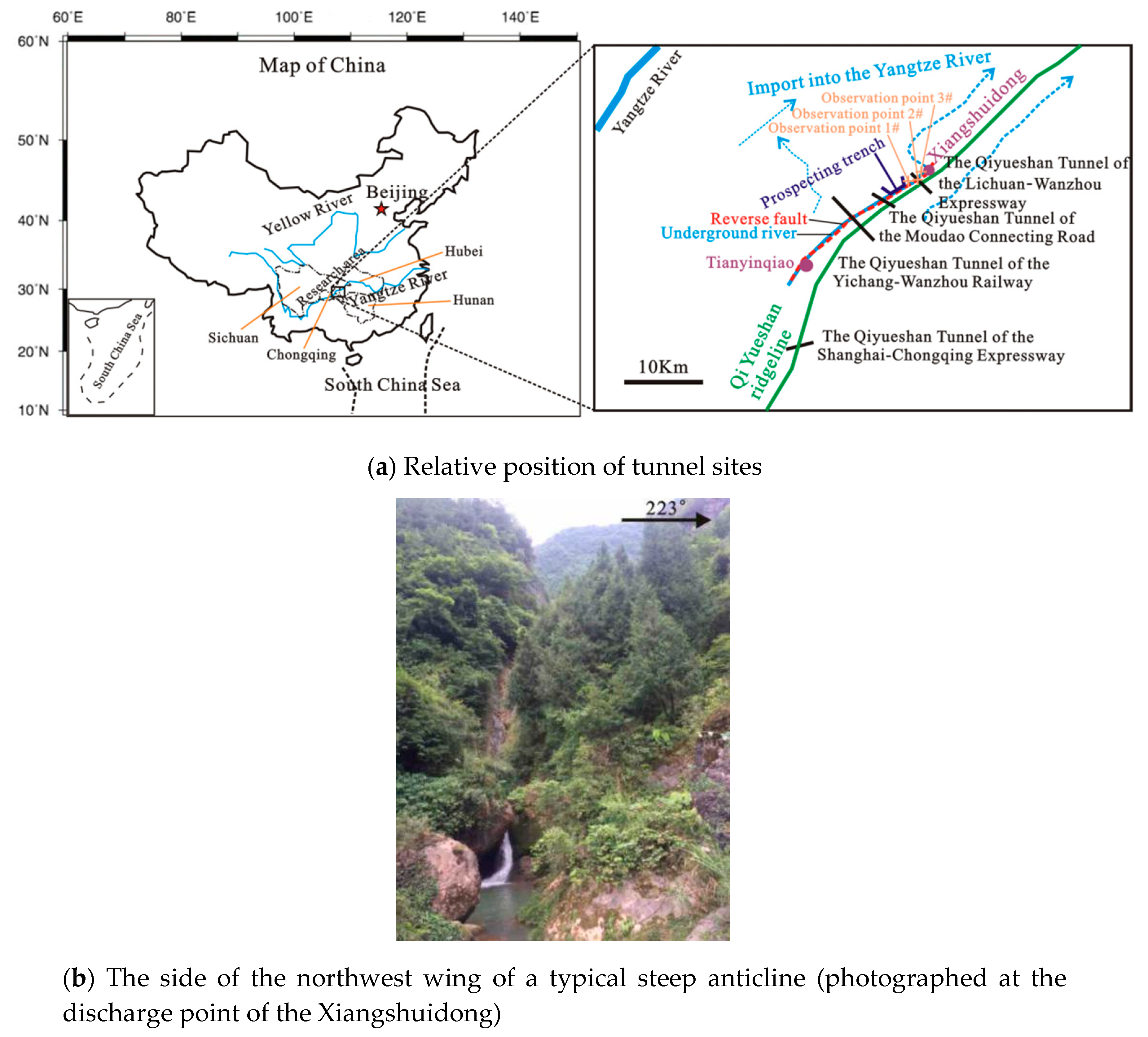
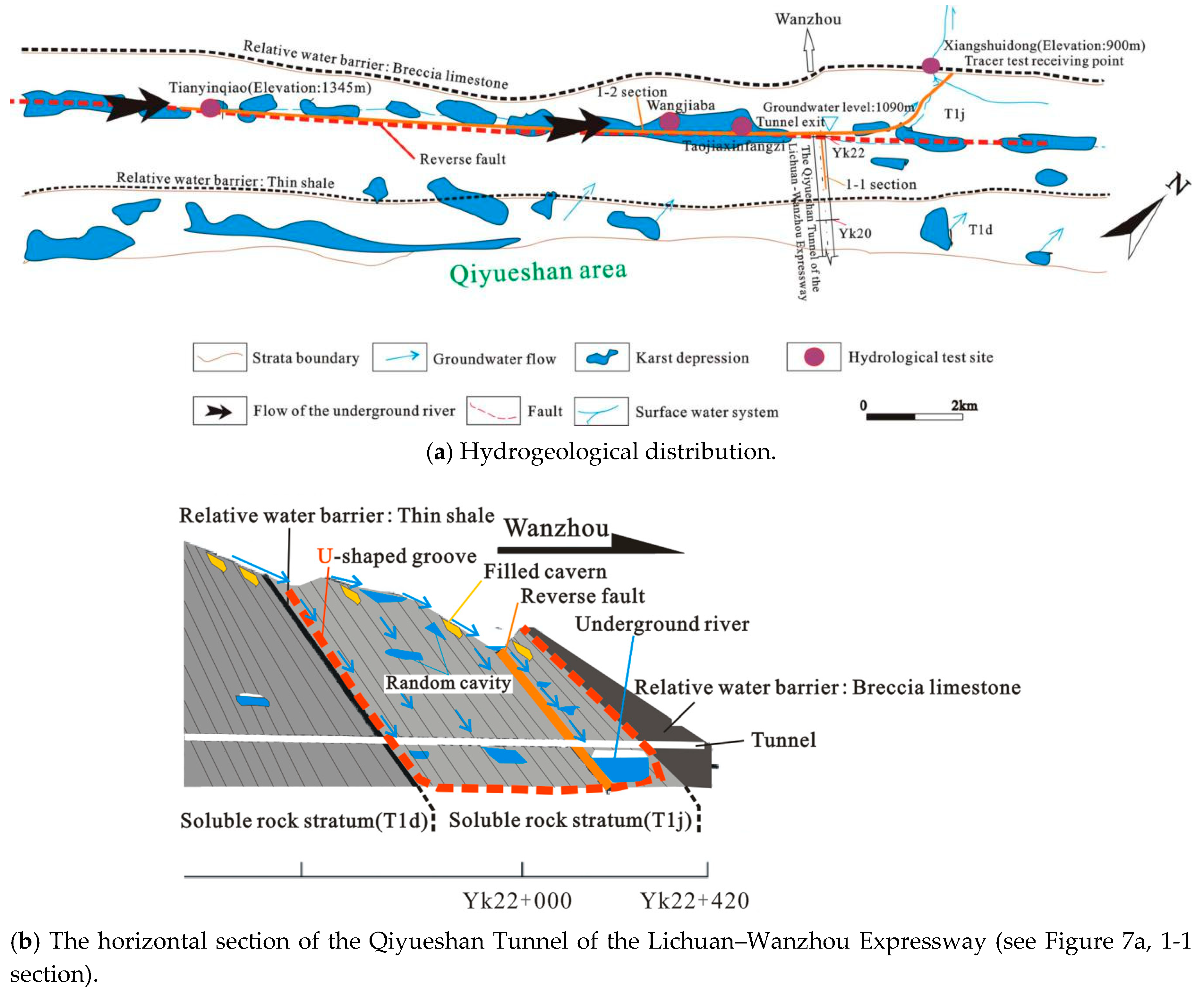
The Qiyueshan Tunnel is located in the transition zone between the western Hunan–Hubei and eastern Sichuan tectonic belts (Figure 1a). The tunnel crosses the Qiyueshan anticline, and the anticline has two asymmetrical wings. The occurrence of southeastern wing is at about 115–70° and the occurrence of the northwest wing is at about 320–60°. Qiyueshan area is a huge obstacle to the control of the Enshi–Lichuan section of the Hurong Expressway and other highway and railway projects in the southwest (Hubei and Chongqing sections). It extends for 226 km and its surface elevation ranges 1200–1700 m. The geological structure is relatively complex (karst microgeomorphs such as karst gullies, karst grooves, funnels, and water holes are developed in the tunnel site). For example, during the construction of the Qiyueshan Tunnel of the Yichang–Wanzhou Railway, a branch of the underground river was exposed to water inrush accidents, resulting in many deaths and property losses. Its surface water development is not high, but the groundwater system is mainly karst water, which is mostly stored in karst pipes. Groundwater is mainly supplied by atmospheric rainfall, and, due to high and steep mountain potential, it is rapidly transferred to karst depressions and water holes to enter karst aquifers through the surface, and is eventually excreted in the form of karst springs or water discharge points through dissolution cracks and pipeline runoff (see Figure 1b). According to incomplete statistics, many karst water bursting accidents have occurred when crossing the mountains during construction of the Yichang–Wanzhou Railway and the Shanghai–Chongqing Expressway, which is a typical high-risk tunnel site [14]. The underground river studied in this paper is roughly parallel to the mountain range along the reverse fault; the strike is about 54°. It is located in the karst aquifer group from the Qiyueshan anticline west wing; that is, Daye Formation (T1d)–Jilingjiang Formation (T1j), Triassic.
3. Reverse Fault Control Mechanism of Underground River Development
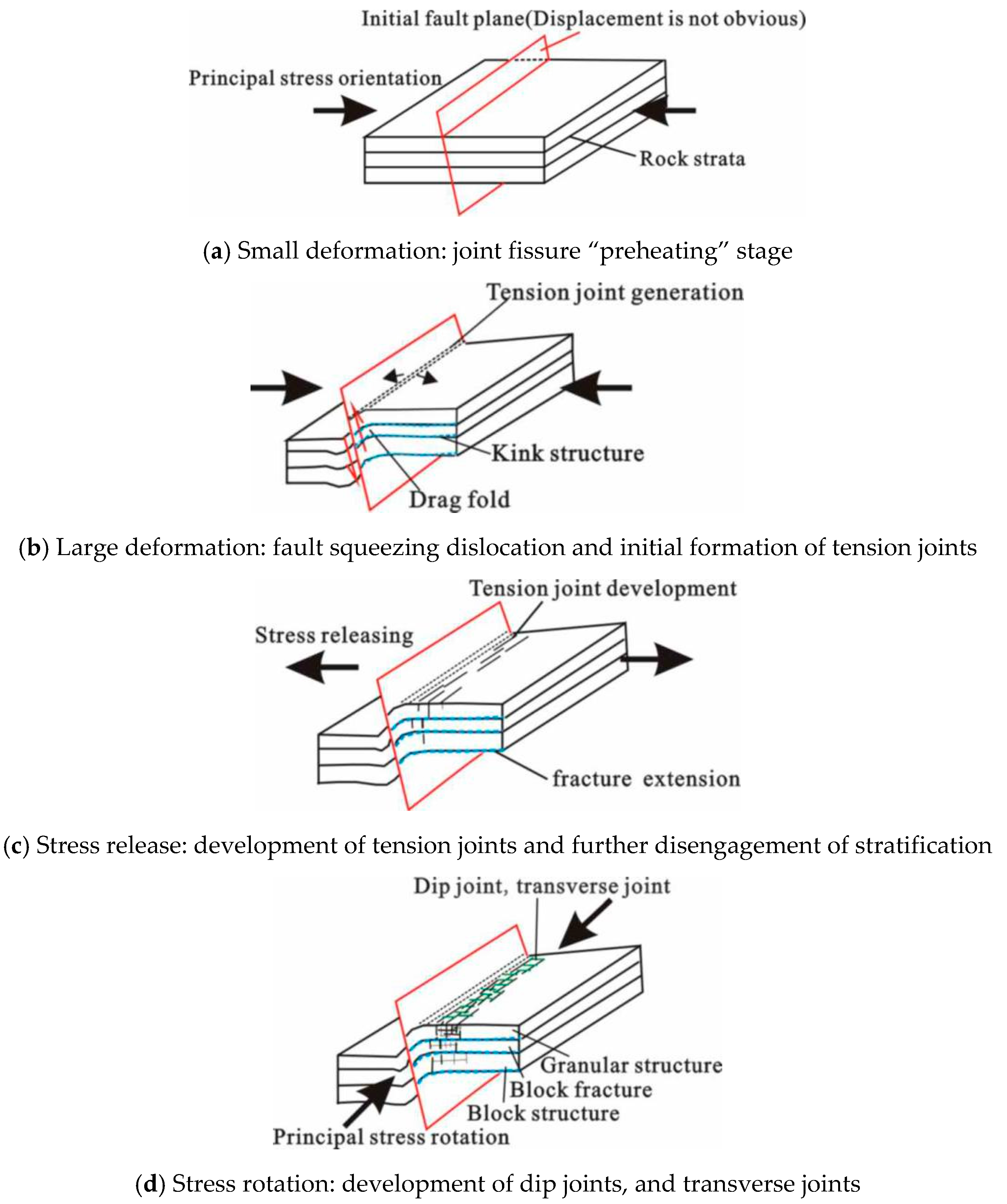
Traditional studies have suggested that karst pipelines and even underground rivers developed by faults are mainly controlled by tensile faults. This view has long been recognized by scholars in the karst world [12,13]. In the study of the control effect of a fault structure on karst development, it is generally considered that the fracture in the fault zone of the reverse fault is closed, which is not conducive to the flow and occurrence of groundwater; thus, the karst in the reverse fault zone is hardly developed, so does not attract enough attention. However, with the continuous maturation of understanding and experience, the rock mass near the hanging wall of the reverse fault can form large-scale unicorn caves and even underground pipelines under certain conditions and scales [15]. To this end, we first give an new analysis from the stress state of the reverse fault formation process (Figure 2), which is called the new four basic stages. According to Reference [15], from the perspective of rock mechanics, the formation of the reverse fault can be divided into three basic stages. In the first stage, under the action of principal compressive stress, the rock mass first undergoes elastic deformation to elastoplastic deformation, forming joint fissures, which is the initial shape of the reverse fault (Figure 2a). In the second stage, the reverse fault develops and forms drag folds on the fault zone (Figure 2b), and tensile stress states occur at various locations, forming local fracture zones and interlaminar fracture zones. In the third stage, the main stress is gradually released and dissipated. At this time, the structure is reversed, and the reverse fault is in the state of extension (Figure 2c), resulting in large-scale development of the longitudinal and vertical fissures at the upper plate, and the openness of the layer increases. In addition, if the direction of the principal stress is rotated, the development of the dip joints and transverse joints will occur, and the layering and the joint formation formed in the previous three stages will easily form a small block of the cut subsidence (Figure 2d), which will further aggravate the development of karst. Regarding the vertical zoning of the fault-attached rock mass from the surface layer to the deep part, as proposed by Wang et al. [16], according to the degree of weathering and tectonic action, it is easy to divide it into three structural levels (granular structure, block fracture structure, and block structure; see Figure 2d).
Below, we explain the effect of the abovementioned fissures on the field survey and the structural traces.
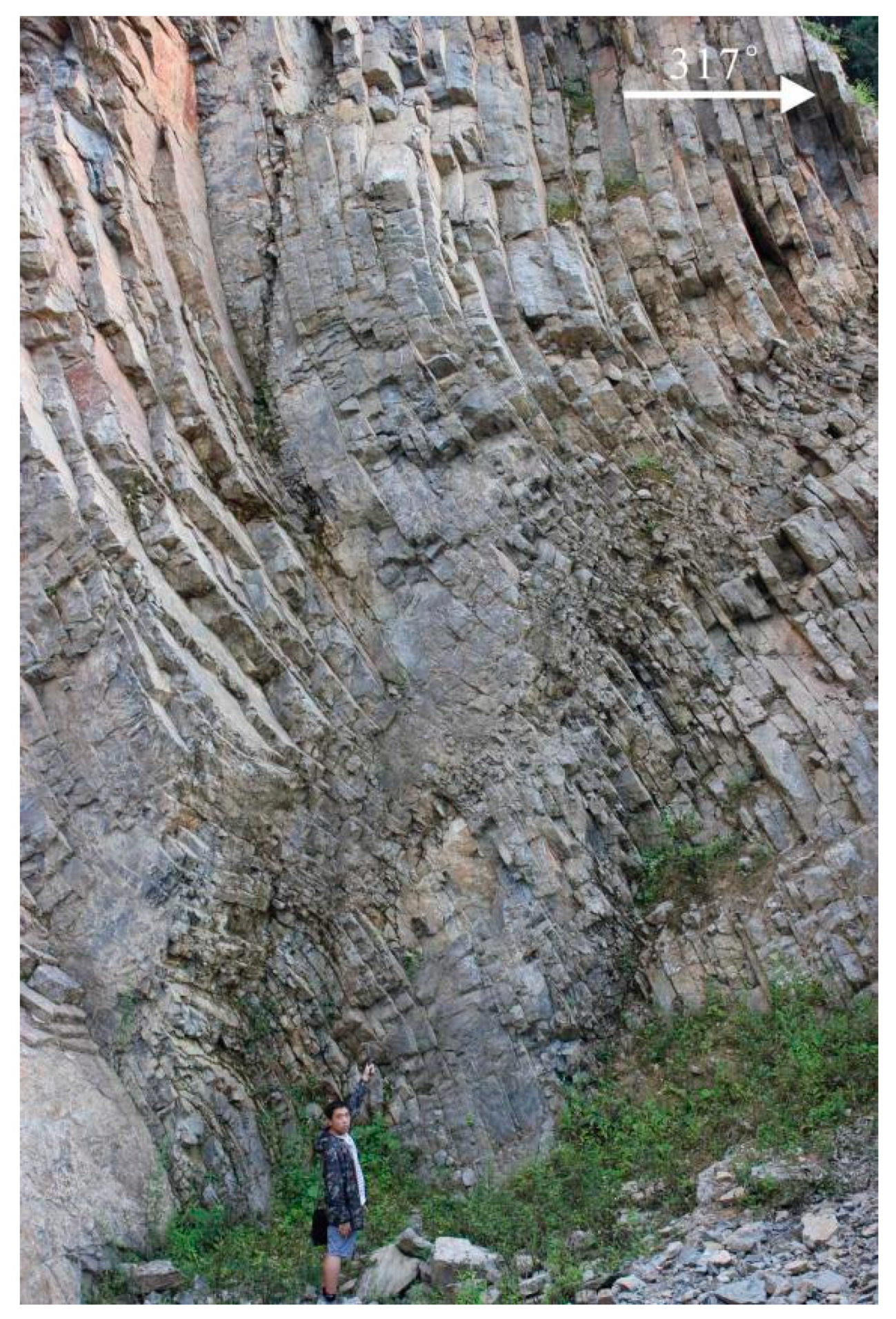
First, natural stratifications themselves provide good storage and transportation space. Dong et al. [17] found through a field geological survey of karst development zones that, among 83 karst caves, 60% had undergone stratigraphic development. It can be seen that, with the increase of depth (the rock mass gradually gets better and there are relatively few fractures), the stratification gradually formed the dominant water control structure surface. Bai et al. [18] pointed out that the structural characteristics of rock formations would make up for the insufficiency of soluble rock dissolution to a certain extent, and even become the main factor affecting karst development. According to the data of karst caves in China, the contribution rate of bedding plane landslides and tectonic fault structures to karst bodies is much higher than that of the original rock stratifications, which is the main water-controlling preferred plane [19]. According to previous research, there have been five periods of structural superposition in the Qiyueshan area [20]. Combined with field investigation and analysis, we believe that the stress action represented by NW–SE compression–release is the main controlled stress field (i.e., the controlled stress field of the development of a thrust fault), by which many “knee-joint” structures were developed in the lower Triassic Jialingjiang Formation (with a strong dissolution horizon) of the Qiyueshan anticline west wing (Figure 3). According to field surveys, these secondary structures are mostly developed in weak strata, such as medium-thin-layer limestone and mudstone, which are interlayer parasitic fold belts, indicating the bedding shearing during the development of longitudinal bending folds, resulting in layer slippage. Subsequent introduction of NW–SE compression–release causes the rock layer to be further disengaged (corresponding to Stage 2b), which provides better conditions for the formation of good interlayer dissolution (corresponding to Stage 2c). According to onsite compass measurements, the dip angle of the rock layer is mostly ~20–60° (Figure 3), which is favorable for karst development, and the layered rock mass is easily broken and detached due to stress concentration at some bends.
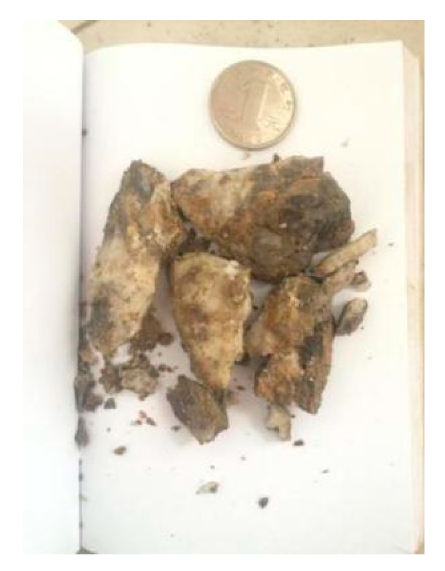
Secondly, it is generally believed that the development of fractures in the two sides of a simple reverse fault is relatively small, especially in the fault footwall, where the development of fractures is the lowest and water abundance is poor [21]. However, as shown in Figure 2d, when a certain scale of thrust faults (such as faults with a length of more than ten kilometers or even dozens of kilometers) are under the action of rotating compressive stress (mainly NE–SW compression, and even E–W and N–S compression superimposition [19]), the rock mass structure is unstable. We randomly selected fractures to measure their aperture. According to the authors of [22], the cracks at the outcrop showed good opening degrees, most of which were medium-wide to very wide (see Table 1). In addition, most of them had no filling—or occasionally, a soluble salt filling—in the tunnel, and thus were easy to break and had low strength and poor water resistance (Figure 4). As the depth increased, the aperture grade of the fracture decreased.
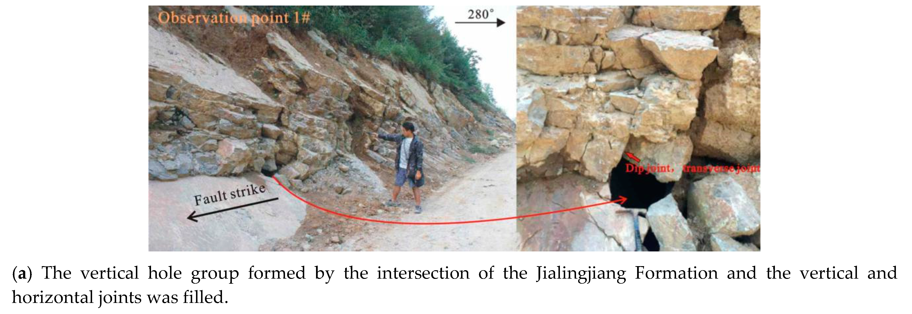
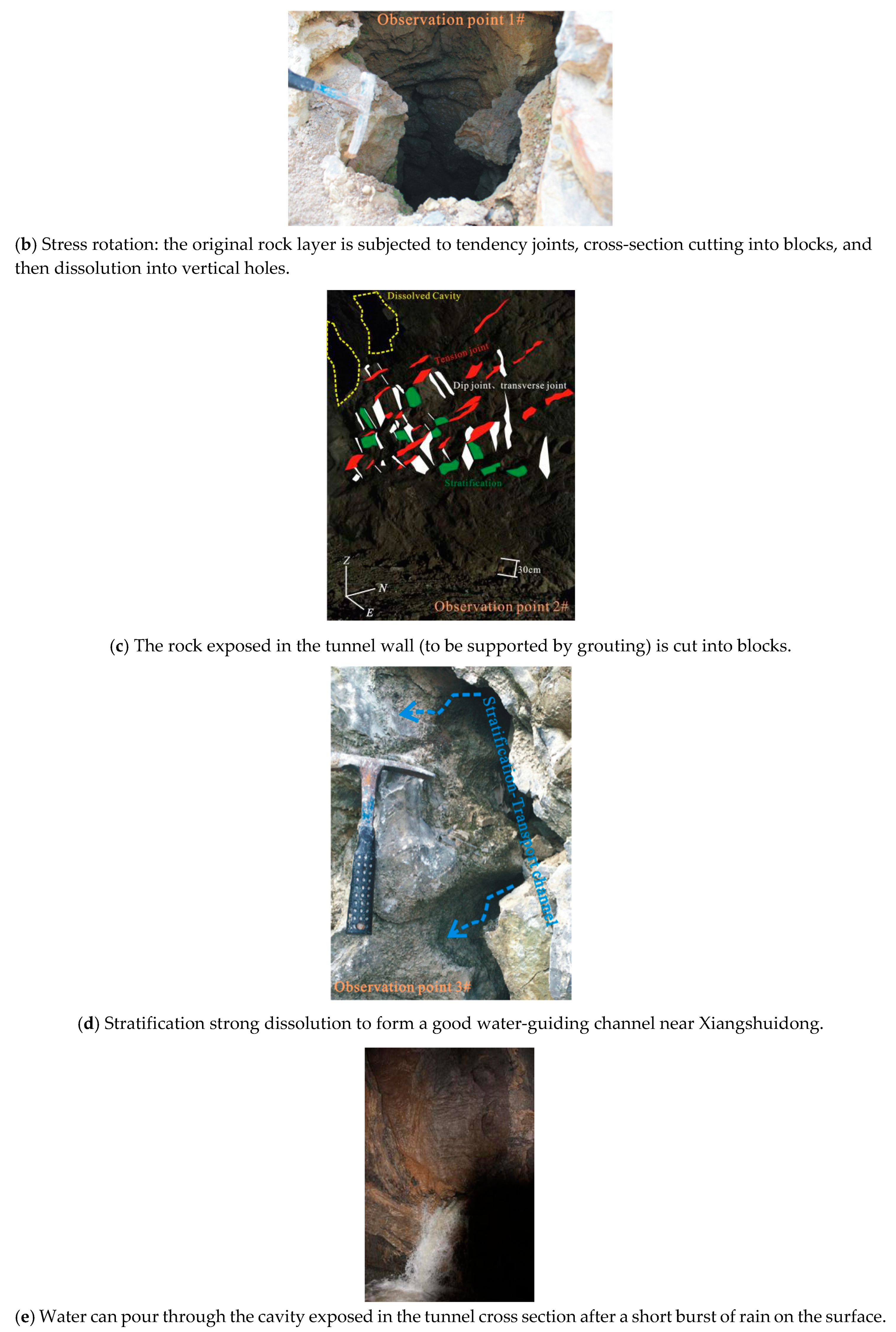
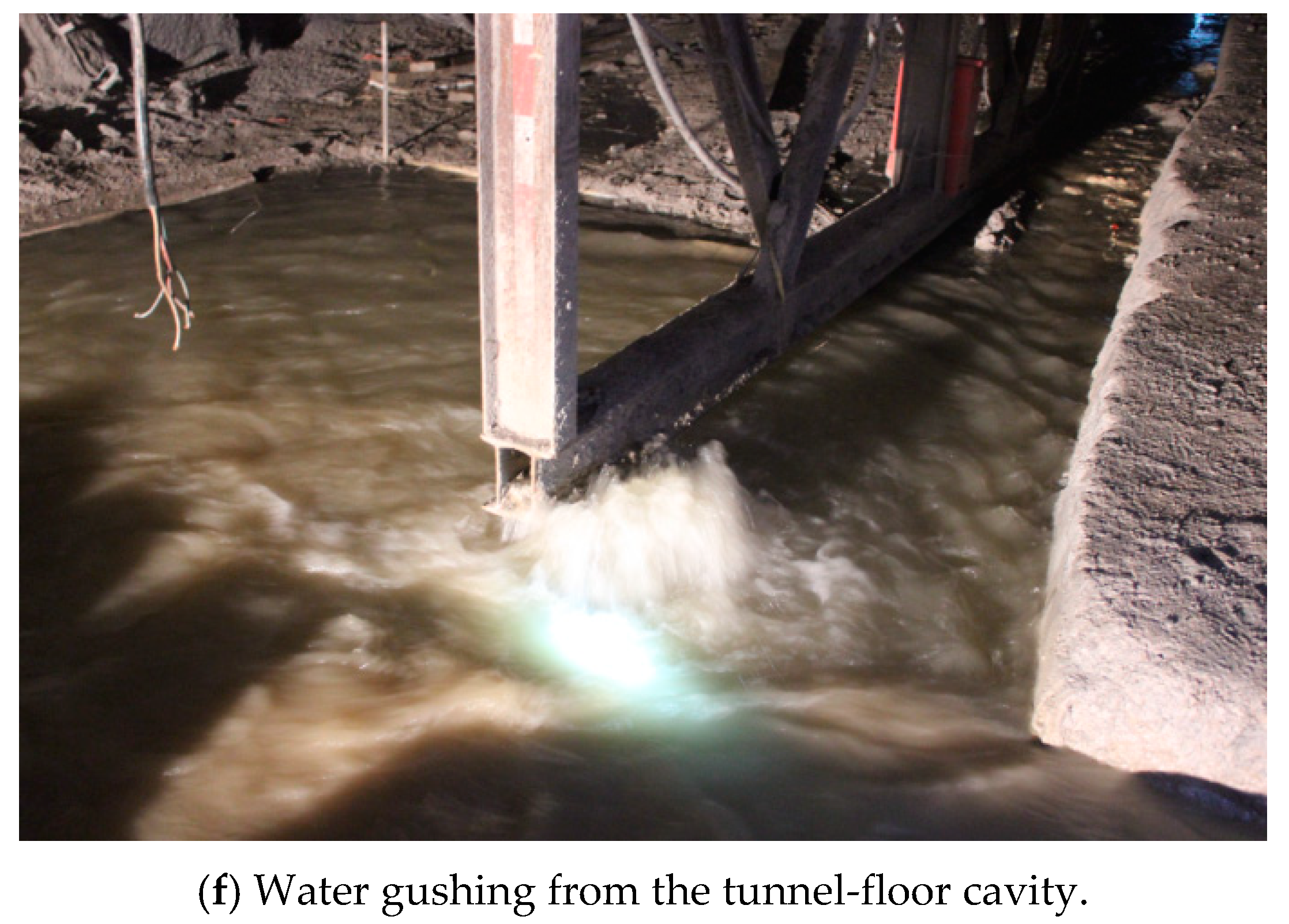
During the outcrop survey, it was also found that the horizontal karst was not easily formed in a certain range of the surface and was easily filled with mud (Figure 5a), mainly developing vertical corrosion holes (Figure 5b). In the field, we used a geological hammer to hit the tunnel, which would easily lead to a large amount of falling pieces and randomly mixed small dissolved cavities (Figure 5c). As found through observation in the tunnel crossway, even in the presence of concrete lining, this cross-cutting mode is prone to falling blocks, poor self-stability, and severe water seepage in some crack surfaces, among which tensile cracks and bedding faces have obvious strong corrosion (Figure 5d). The extensive development of this bedding karst structure provides good space conditions for groundwater storage and migration. From structural characteristics, it can be summarized as: the rock mass near the surface of the fault zone has a granular structure, the stability is poor, and it is easily filled (Figure 5a). However, in the block cracking structure of the tunnel, the rock mass can be self-stabilized and the conditions for hole formation are good (Figure 5c,d): the bedding expands laterally to form a larger cavity, where water surges through the tunnel quickly after heavy rain (Figure 5e,f). The stability of the block structure is the best, and generally not conducive to the formation of a good channel.
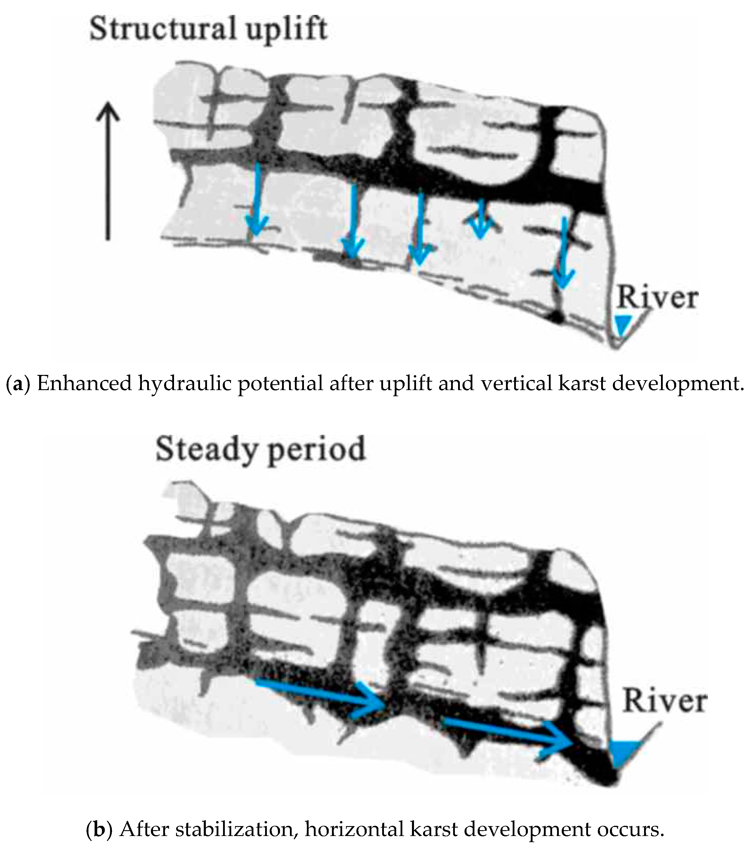
One of the other important reasons for the formation of smooth passageways above is the result of multiple periods of tectonic uplift in the region; this research area belongs to the southwestern part of Hubei Province and has been affected by uplift since the Neoid period [23]. After each uplift, a relatively stable period completes a karstification process, forming a multilevel karst peneplain, terraces, and corresponding multilevel karst caves, which gradually form a complete hydrodynamic recharge channel. The tunnel site is mostly within the level 2 (elevation 1200–1300 m) and level 3 (elevation 900–1100 m) karst peneplain, which means it experiences strong hydrodynamic conditions from the upper-level catchment area; this process mainly accelerates the expansion of runoff to karst (Figure 6).
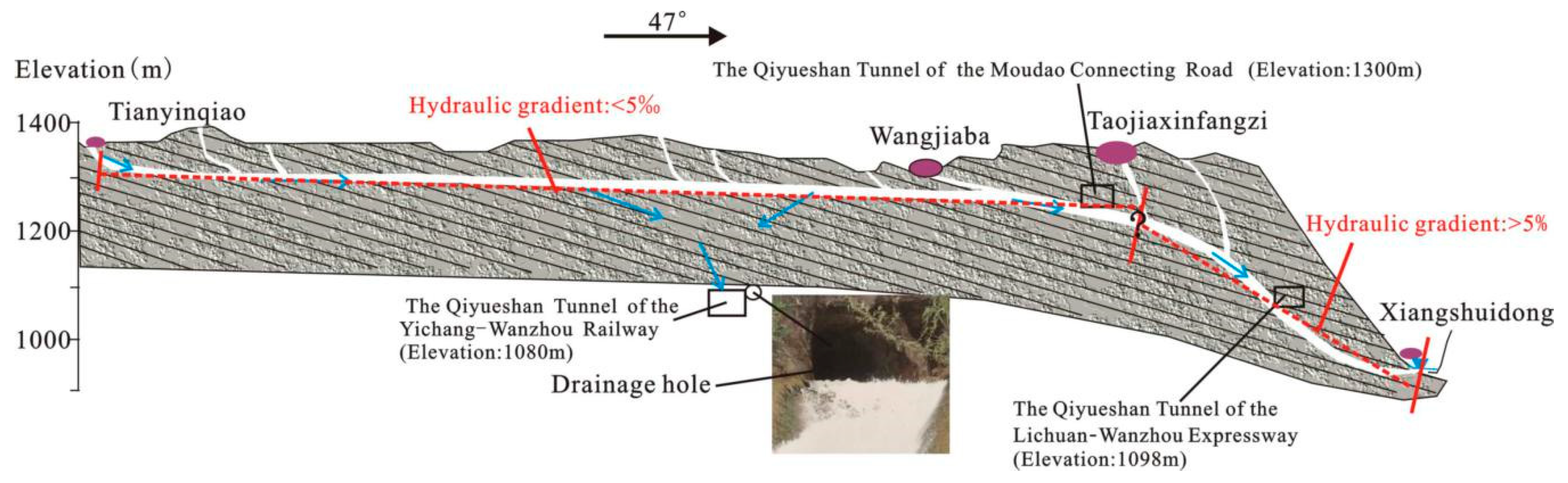
In conclusion, the cutting joints formed under the influence of multiple periods of tectonic stress, especially the stratifications with large aperture degrees and tensile joints, provide a good channel for continuous erosion of the water body, thus meeting the condition of controlling the reverse fault to form a large underground river. At the same time, the Earth’s crust is uplifted and rainwater is collected at steep slopes. In the early stage, infiltrating groundwater and surface water have strong downward and horizontal potential energy, the long-term strong hydrodynamic action continually erodes the rock, and the vertical dissolution is strengthened, especially when the rock body in the hangwall area near the reverse fault is carried away by dissolution. It is worth mentioning that, combined with the hydrological survey data, the hydraulic gradient of the upstream segment (Tianyinqiao–Taojiaxinfangzi) is extremely flat, at less than 5‰, while the average hydraulic gradient of the downstream segment (Taojiaxinfangzi–Xiangshuidong) is very steep, at more than 5%. The uplift process may cause the underground river to appear incongruous in the section; that is, the hydraulic gradient in the section is very inconsistent. In addition, there are relative barriers (such as shale, breccia limestone, etc.) on both sides of the strong karst beds, which provide boundaries that concentrate the confluence of water in the development of the scale and degree of the underground river, causing the cutting of a U-shaped groove (Figure 7). Finally, an unimpeded underground river is formed (Figure 8).
4. Hydrogeological Method Verification
From the perspective of hydrogeology, we found that the dynamic characteristics of the flow are closely related to rainfall, and the dynamic changes are large, which reflects the excellent connectivity of the underground river, the relatively perfect development of the pipeline system, and the large scale (Figure 9). This may prove that the development degree and supply, or discharge fluidity of the river controlled by the reverse fault, can also be very mature. Large thrust faults that extend for tens of kilometers can also form unimpeded underground rivers, breaking the old belief that large-scale river systems cannot be formed in the karst around reverse faults.
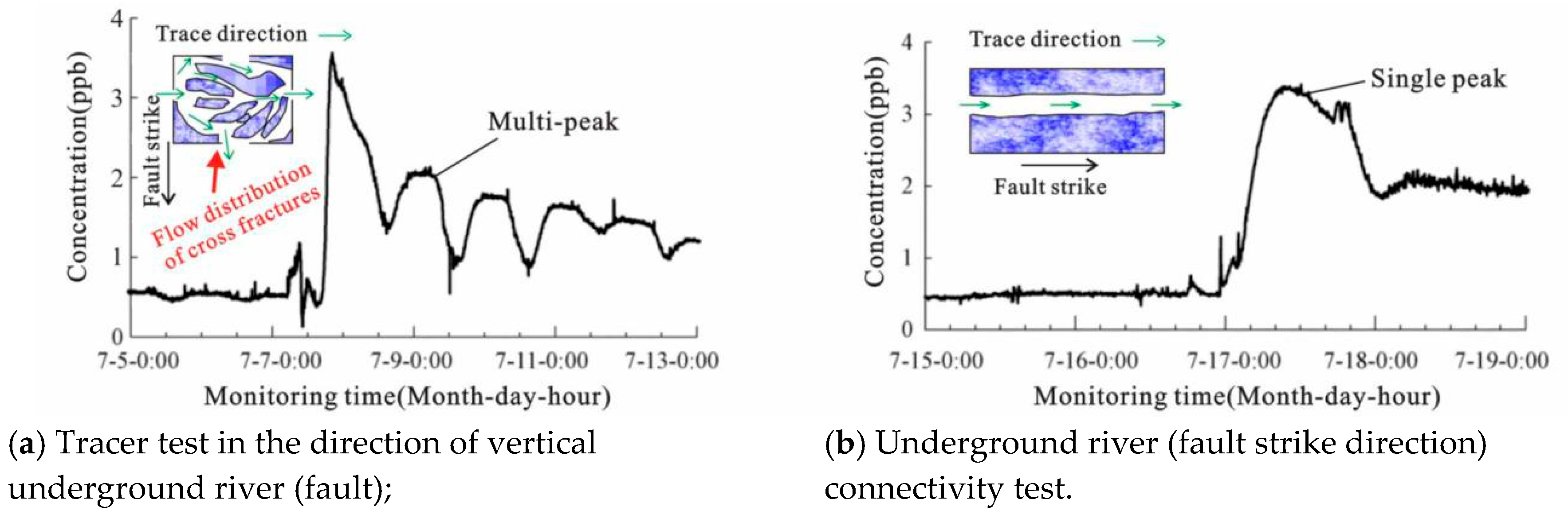
Finally, considering that the tracer test has become a powerful method for exploring more mature karst hydrogeology [26,27,28], in July 2015, we introduced a high-precision tracer test method after heavy rain between Wangjiaba and Xiangshuidong, and found that the karst pipeline was still relatively smooth, especially after the rainstorm. Although the underground river system was later captured by the Yichang–Wanzhou Railway’s drainage hole, it became two subsystems; tracer data between Wangjiaba and Xiangshuidong show that the underground river is still guiding water (Figure 10). We further pursued the tracer data of the Yichang–Wanzhou Railway construction period [29], finding that the flow velocity in the direction of the underground river is 2.4 × 10⁻¹ m/s, while the vertical development of the cave flow rate is 1.2 × 10⁻¹ m/s. The cross-fault (footwall) perpendicular to the fault direction is relatively weak, and its flow rate is reduced to 4.1–6.9 × 10⁻² m/s. As can be seen from the tracer curve, it can be further inferred by comparing the curvilinear karst morphological model diagram given in the literature [30]: a body of water perpendicular to the direction of the underground river may have traveled through several series of small karst pipes with relatively weak development, and its curve is multimodal (Figure 10a); in the process of resupply, when more open pipes are encountered (the direction is the same as the underground river), the fractures may lead to flow distribution and some water bodies may be lost, such as shown by some other similar results, in that permeabilities measured parallel to the fault dip were up to 10 times higher than along the fault strike permeability [31]. The underground river appears as a single mature large karst pipeline with a single peak curve (Figure 10b). The vertical permeability and fault permeability of the fault can be one order of magnitude lower; therefore, it can be said that the development of the underground river along the strike line of the reverse fault is advantageous. The analysis of hydrogeological data can verify the correctness of the results most directly. Therefore, dynamic monitoring and multiseason real-time tracer tests must be carried out under highly specific conditions.
5. Discussion
5.1. Selection Basis and Suggestions of Tunnel Design Elevation Relative to the Location of the River
The selection of elevation plays an important role in the selection of geological lines. It can be concluded from consideration of the structural changes of the vertical rock mass of the fault structure, and the relative position of the development of the underground river can be delineated, which can provide a reference for the design of tunnel elevation. According to the viewpoint of Xiao’s new structure for controlling water [32], while considering the vertical direction of the fault [16] in combination with the actual survey, the information presented in Table 2 was obtained. The infiltration zone is in the shallow part below the ground, but the amount of water is often not particularly large due to the effect of near-surface filling; and the runoff zone is generally between 50–60 m and 150–200 m below the ground (mainly in block fractures or block structures). The block fracture structure should be a favorable area for the development of large pipelines and underground rivers. In the detained zone below the runoff zone, in general, the water content in the fractures is small and the mobility of the water is relatively poor. Under normal circumstances, it can act as a resistive water layer.
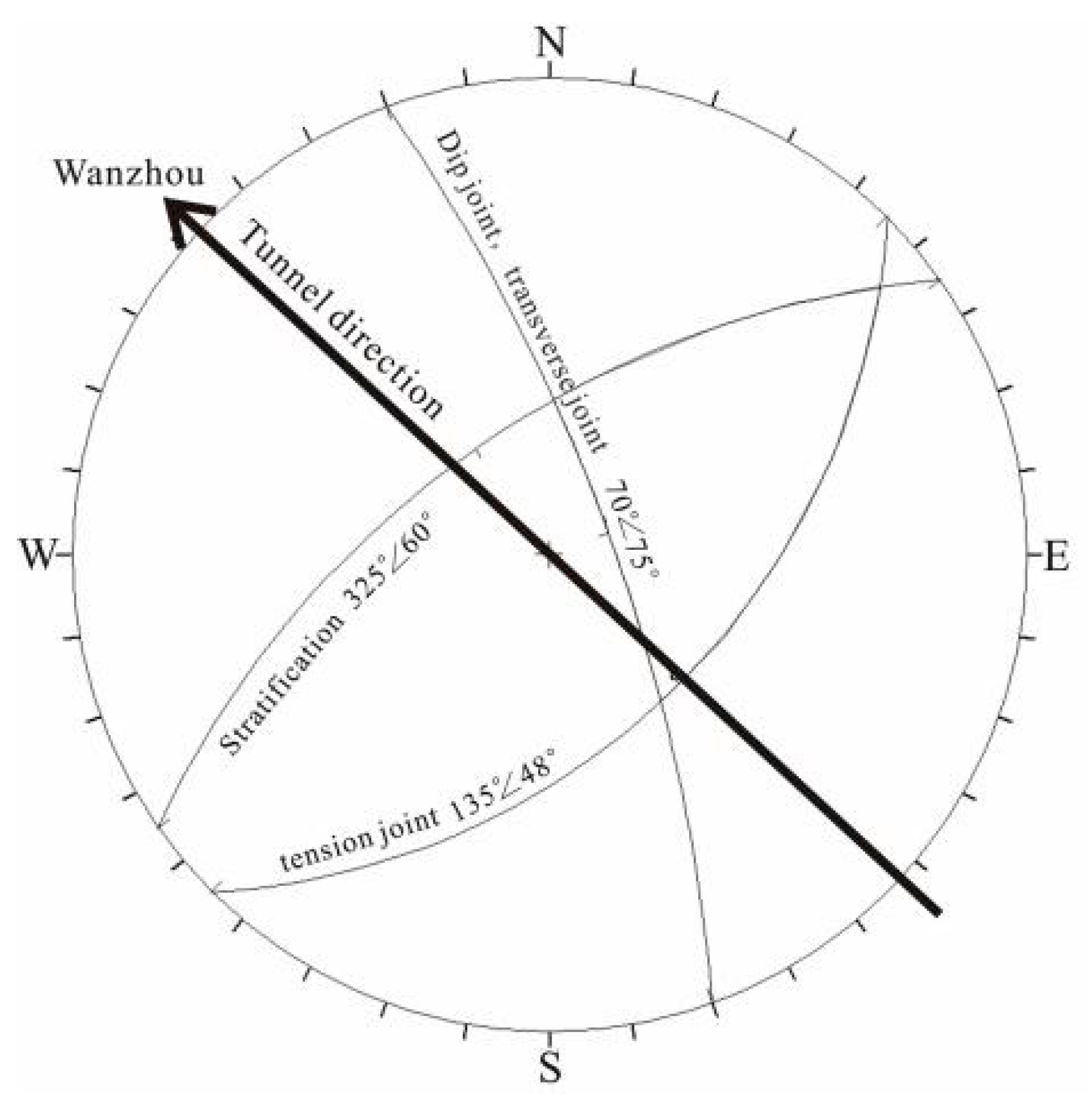
Throughout the tunnel construction cases, most of the above three types of structures will inevitably pass through faults in line selection and elevation design (Table 2). Although the granular structure has poor characteristics, it can be stable at 22.25 m below the surface, as found through the numerical simulation study on the safety depth of the Qiyueshan Tunnel site [34]; therefore, below this depth and with the corresponding support and reinforcement measures, a tunnel can be safely constructed. Is it absolutely without risk to cross the block fracture or even the block structure below the underground river? Practice has proved that crossing the block structure in the karst area is not foolproof; for example, Deng [35] determined that the tunnel passing under the underground river, even if there is no fault, is affected by the recharge of the bedding layer and still carries the risk of experiencing great water inrush. From the actual dynamic excavation process, it can be seen from the theoretical analysis of block theory [36] that, under the tunnel excavation, a free surface is created, and that under the action of engineering and self-weight, development of the key block is started because the strength of the sliding surface was insufficient to resist the sliding power, and this may lead to interlocking multiblock instability. We plot the stereographic projections by identifying the occurrence information (according to the preliminary statistical characteristics of the appearance in Figure 5c), as shown in Figure 11; this type of intersection mode is mainly prone to instability and blockage in the vault, easily producing tetrahedral pyramidal blocks, and other types of blocks are generated depending on the fracture spacing [37,38]. If located under the underground river, the excavation space causes the falling of blocks to occur sooner under the action of water pressure, providing space conditions for the karst water to enter, such as when the Qiyueshan Tunnel of the Yichang–Wanzhou Railway caused a landslide when crossing this type of area, causing a serious water inrush disaster [33].
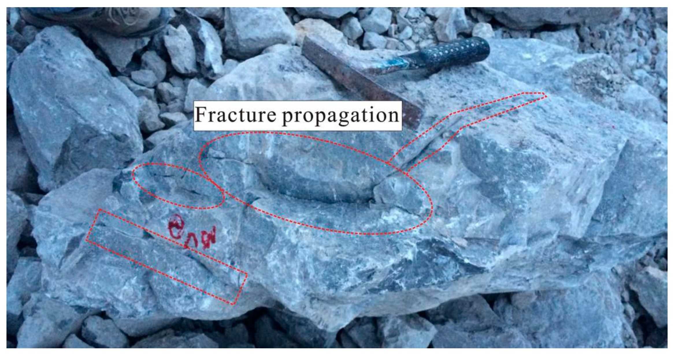
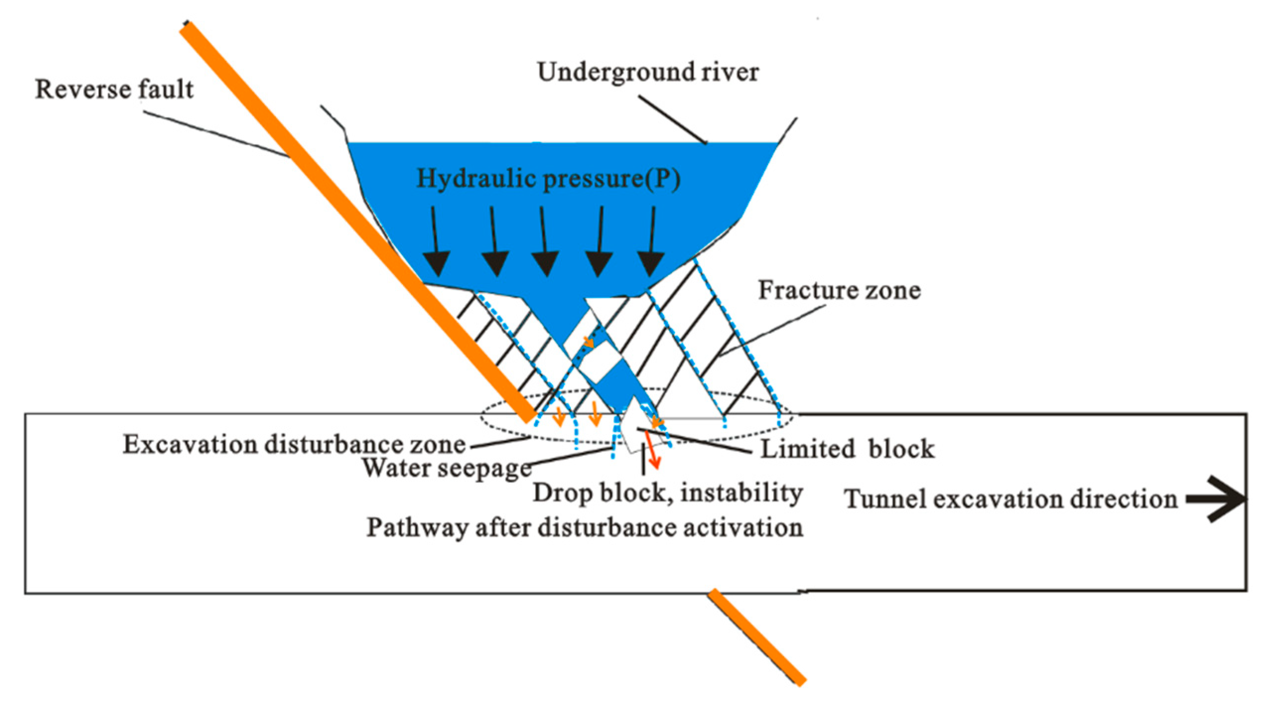
According to further analysis of stress changes, especially in a short time after the excavation disturbance, the additional stress and the confining pressure change are actually generated [39], the additional stress may cause the fractures to be more open, and the change in the confining pressure will deteriorate the fault zone lithology (Figure 12); this can also transform the original relatively water-blocking fault zone into the dominant water-control surface. Under the huge water pressure of the upper underground river, coupled with excavation disturbance, the underside will evolve into a seepage channel from the vulnerable fractures between the underground river and the excavation, which will strengthen the capacity of the seepage channel connection after the falling of blocks, increasing the water inrush risk of the tunnel (see Figure 13).
In general, when the well-developed and confluent underground river has a spatial relationship with the tunnel between the upper and lower sections, the fault between the two easily forms a high-pressure water-rich fault zone with strong hydraulic recharge. The tunnel will encounter instant or delayed water inrush during the construction of the tunnel underneath the underground river. The earlier design of the Qiyueshan Tunnel of the Yiwan Railway through the bottom of the underground river has caused several large-scale water inrush events, indicating that, when the fault is present, the nearby rock mass is disturbed, and the depth of influence can extend down about 200 m; therefore, crossing the rock mass too close to the bottom of the underground river should be avoided. This requires the design elevation to be fully considered at the beginning of the design. We can choose position a tunnel at similar elevations to the river; for example, the Zijinshan Tunnel is designed to cross the underground river at the same height, the necessary drainage hole is set in consideration of the rainstorm, and the drain hole is set 2 m above the drain point [40]; the tunnel elevation can also be set at slightly higher and lower elevations relative to the hidden river; for example, at points where the Wulong Tunnel passes safely through the longitudinal slope and the water flow of the underground river, the tunnel elevation was designed to be 20 m above the elevation of the underground river [41]; other examples are given by the Qiyueshan Tunnel of the Lichuan–Wanzhou Railway and the Qiyueshan Tunnel of the Moudao Connecting Road (Figure 7a and Figure 14), where the elevation of the tunnel was set on the runoff elevation line of the underground river and the tunnel construction process was carried out smoothly without causing any serious water inrush accidents. Therefore, we believe that it is generally safe and economical to set the elevation of the tunnel projects to be constructed in this region to be slightly higher than that of the river.
5.2. The Necessity of a Reasonable Multisource Exploration Method
At present, due to the problems of surveying, design precision, and construction quality, engineering technicians often encounter various geological disasters during tunnel construction, among which water inrush and mud burst events are the most frequent. Before the construction of the Lichuan–Wanzhou Expressway Tunnel in Qiyueshan area, it was estimated that it might cross the hidden river and that there would be a risk of water inrush. However, during the excavation, the project was completed without revealing the underground river. In fact, we do not fully understand the exact location relationship between the tunnels and the underground river, which means that the current exploration techniques still cannot accurately locate the turning point of the underground river (as shown by the question mark in Figure 13). Hjerne et al. [42] conducted a long-term nuclide migration tracing test of multiscale structural planes of rock masses in the project of the famous underground engineering Aspo hard rock laboratory TRUE in Sweden, pointing out that it is necessary to identify multiscale structural planes in rock masses. There are still many technical challenges in hydrogeological parameters, and the complicated path of the joint system remains difficult to understand. It is suggested that future research should aim to strengthen the accurate description of the spatial structure of the rock mass joint system. Zhang et al. [43] considered the study area to be too large, so the characteristic parameters of the fracture were identified by means of drones; in the case of outcrop steepness, the size of the fault and the division of the influence zone were determined by means of geophysical and photogrammetry [44]. Furthermore, Zhang et al. [45] pointed out that when the crack path is clearly identified, the fault avoidance distance can be given more accurately, the GPS-RTK is used to trace the cracks on the flat outcrop surface, and the possible seepage range of the fracture is determined. Therefore, in the large karst areas, where the karst cavity has a strong specificity of development, more attention should be paid to the form and development degree of water channels. People are beginning to realize the importance of comprehensive interpretation of multisource technology. It has been proved by practice that a single test method can no longer meet the needs of survey accuracy at the present stage, and may even lead to serious miscalculation. However, we should not excessively pursue various technologies which would simply pile up, causing waste. The key is to develop appropriate reference standards. As Yan [46] pointed out, it is necessary to not only increase the accuracy of ground geophysical exploration at great depths, but also carry out research on the application of techniques of tunnel investigation such as airborne geophysical prospecting and horizontal directional drilling combined with borehole geophysical exploration. In addition, from the karst perspective, Ficco and Sasowsky [47] pointed out that current laws for karst aquifer protection are unsystematic and many documents presenting suitable guidelines for karst aquifer management are not legally binding, and noted the problems that arise with a lack of specialist evaluation and differences in approaches. However, relevant scholars are actively making suggestions, such as Zhang et al. [48], who pointed out that the use of tracer test after the fault zone identification can improve the success rate. It is considered that the multisource survey technology and standards in the process of field geological parameter identification should be further established and improved: Deng [49] suggested bringing the content of a special geological survey for tunnel risk into a professional standard titled code for geological investigation of railway engineering. Guo et al. [50] divided karst tunnels into different categories according to certain criteria and proposed the principles of classification management and information construction. This would also be an important direction for further research.
6. Conclusions
Unlike randomly distributed cavities, caves, etc., large-scale underground rivers can be effectively controlled. Taking the Qiyueshan Tunnel site project as an example, we believe that the reverse fault also has the possibility of developing a large underground river. Among them, with the increase of depth, the faulty rock stratum near the fault core is especially related to the development of the underground river. It plays a significant role and becomes the main channel of the catchment. In addition, due to the rotation of the principal stress direction, the tendency joints, stratification, and transverse or dip joints develop into sinks, water-conducting holes, and cavities under the action of water flow dissolution. In addition, the multistage tectonic uplift provides strong hydrodynamic conditions for the runoff zone, facilitating the expansion of the horizontal and downward spaces of the horizontal channel (underground river).
In terms of tunnel elevation selection recommendations, the bulk structure can be selected within a certain safe depth under certain numerical simulations; when it is selected to pass under the underground river, additional stresses are generated due to excavation disturbances and fractures are generated. The fractured rock mass near the fault and its hanging wall is likely to form a strong high-pressure water-rich channel under the action of the upper underground river. Under excavation disturbance, the rock mass in the lower detention zone of the underground river is not stable and reliable. Through the practical engineering analysis, it is shown that, when there are faults and unicorn channels, the tunnel should be designed as far as possible above the level of water in the rivers. If we have to build the tunnel under the underground river’s elevation, we conduct geophysical prospecting with a tracer to effectively identify areas of possible transmission channels, and then make the necessary identification of parameters of the rock mass structure type and the stability analysis of surrounding rock after excavation, in combination with a numerical simulation method to further demonstrate the feasibility, thus making a comprehensive, targeted excavation plan.
The control effect of faults on karst development has many influencing factors. This article is only based on the study of previous research materials and fieldwork. The related elevation design needs to be further studied systematically.
Author Contributions
P.Z. conceived and wrote the paper; Z.H. and S.L. reviewed and made corrections to improve the paper; and P.Z., S.L. and T.X. analyzed the data. All authors read the full paper and agreed to its publication.
Acknowledgments
Associate Professor Zhenhao Xu in Shandong University provided much help in the fieldwork, including internal materials to help the authors understand the regional background more deeply; for this, the authors would like to express their gratitude. The authors also appreciate the aid provided by the reviewers and editors to improve the paper.
Conflicts of Interest
The authors declare no conflict of interest.
References
- Qian, Q.H.; Rong, X.L. State, issues and relevant recommendations for security risk management of China’s underground engineering. Chin. J. Rock Mech. Eng. 2008, 27, 649–655. (In Chinese) [Google Scholar]
- Zhang, M.; Xiao, G.Z. Techniques to break through the Karst cavity by sluice outlets in Maluqing Tunnel on Yichang–Wanxian Railway. Mod. Tunn. Technol. 2008, 45, 70–75. (In Chinese) [Google Scholar]
- Peng, J.; Li, X.Y. Water-inrush mechanism during construction and determination of safety distance from the water source in a karst tunnel. Electron. J. Geotech. Eng. 2015, 20, 2345–2354. [Google Scholar]
- Li, L.P.; Tu, W.F.; Shi, S.S.; Chen, J.X.; Zhang, Y.H. Mechanism of water inrush in tunnel construction in karst area. Geomat. Nat. Hazards Risk 2016, 7, 35–46. [Google Scholar] [CrossRef]
- Li, S.C.; Liu, B.; Xu, X.J.; Nie, L.C.; Liu, Z.Y.; Song, J.; Sun, H.F.; Chen, L.; Fan, K.R. An overview of ahead geological prospecting in tunneling. Tunn. Undergr. Space Technol. 2017, 63, 69–94. [Google Scholar]
- Liu, B.; Zhang, F.; Li, S.C.; Li, Y.; Xu, S.; Nie, L.C.; Zhang, C.M.; Zhang, Q.S. Forward modelling and imaging of ground-penetrating radar in tunnel ahead geological prospecting. Geophys. Prospect. 2018, 66, 784–797. [Google Scholar] [CrossRef]
- Huang, X.; Li, S.C.; Xu, Z.H.; Guo, M.; Chen, Y.C. Assessment of a concealed karst cave’s influence on karst tunnel stability: A case study of the Huaguoshan Tunnel, China. Sustainability 2018, 10, 2132. [Google Scholar] [CrossRef]
- Wang, X.T.; Li, S.C.; Xu, Z.H.; Hu, J.; Pan, D.D.; Xue, Y.G. Risk assessment of water inrush in karst tunnels excavation based on normal cloud model. Bull. Eng. Geol. Environ. 2018. [Google Scholar] [CrossRef]
- Luo, X.W.; He, F.L. A Study of Geological Structures Inclined to Disaster and Models of Water Burst in Deep-Buried Long Tunnels. Mod. Tunn. Technol. 2014, 51, 21–25. (In Chinese) [Google Scholar]
- Li, S.C.; Li, X.Z.; Jing, H.W.; Yang, X.L.; Rong, X.L.; Chen, W.Z. Research development of catastrophe mechanism and forecast controlling theory of water inrush and mud gushing in deep long tunnel. China Basic Sci. 2017, 19, 27–43. (In Chinese) [Google Scholar]
- Li, X.Z.; Zhang, P.Z.; He, Z.C.; Huang, Z.; Cheng, M.L.; Guo, L. Identification of geological structure which induced heavy water and mud inrush in tunnel excavation: A case study on Lingjiao tunnel. Tunn. Undergr. Space Technol. 2017, 69, 203–208. [Google Scholar] [CrossRef]
- Yi, L.X.; Zhang, Z.G.; Li, M.D.L.; Li, X.Z. Analysis on monoclinic karst aquifer and its seepage condition—A case in the river bend of Jiangpinghe hydropower station, Loushui river, Hubei Province. Carsol. Sin. 2006, 25, 29–34. (In Chinese) [Google Scholar]
- Yu, Q.S.; Zhang, F.W.; Han, Z.T.; Yu, Y.Q.; Xue, Z.Q. Application of geochemical modeling in the plotting of Karst fissure water systems in the North-south archaic uplift, Ningxia, China. Act. Geosci. Sin. 2005, 26, 375–380. (In Chinese) [Google Scholar]
- Zhou, L. Prediction Method of Conceal Karst Cave based on Displacement Monitoring and Analysis of the Tunnel Rock Deformation Characteristics. Master’s Thesis, Shandong University, Jinan, China, 2017. (In Chinese). [Google Scholar]
- Yan, C.H.; Wang, Y.Y.; Luo, G.Y.; Chen, M.Z.; Chen, X.; Guo, J.H.; Zheng, J. Compressive structure’s control on the Karst development. Geol. Rev. 2008, 54, 343–347. (In Chinese) [Google Scholar]
- Wang, H.; Luo, G.Y.; Li, Y.H.; Lan, H.X. Fault water-hearing capability structure analysis. Hydrogeol. Eng. Geol. 2000, 27, 12–15. (In Chinese) [Google Scholar]
- Dong, Y.; Ju, Y.W.; Zhang, Y.X.; Rui, X.P.; Bu, H.L.; Guo, G.X. Characteristics of joints in karst area and their influence on karstification in Zhangfang in Fangshan region of Beijing. J. Univ. Chin. Acad. Sci. 2014, 31, 783–790. (In Chinese) [Google Scholar]
- Bai, M.Z.; Xu, Z.Y.; Wang, L.J.; Wang, M. Research on the geological condition of Karst water bursting disaster in the course of tunnel caving. J. Railw. Eng. Soc. 2006, 3, 21–24. (In Chinese) [Google Scholar]
- Han, X.R. Karst Hydrogeology; Science Press: Beijing, China, 2016. (In Chinese) [Google Scholar]
- Wang, L.Z.; Tian, Y.; Tu, B.; Zeng, B.F.; Xie, G.G. Paleostress analysis of the Qiyue Shan high-angle anticline in the Lichuan Area, western Hubei Province, China. Geotect Metals 2012, 36, 490–503. (In Chinese) [Google Scholar]
- Tian, K.M.; Wan, L. Research and Evaluation of the Permeability of Anisotropic Fractured Media; Academy Press: Beijing, China, 1989. (In Chinese) [Google Scholar]
- Zhou, Z.F.; Wang, J.G.; Huang, Y. Theory on Dynamics of Fluids in Fractured Medium; Higher Education Press: Beijing, China, 2007. (In Chinese) [Google Scholar]
- Deng, Y.M.; Du, W.S. Hydrogeology problems related to trough valley, karstic water and subterranean flow in Deshengchang of Qiyueshan tunnel. J. Railw. Eng. Soc. 2005, 2, 8–11. (In Chinese) [Google Scholar]
- Tang, M.H. Foundations of Eegineering Geology; Chemical Industry Press: Beijing, China, 2008. (In Chinese) [Google Scholar]
- Chen, H.F.; Xia, R.Y.; Liang, B. Characteristics of karstification and its influence on the tunnel gushing in Qiyueshan, west of Hubei Province. Carsol. Sin. 2003, 22, 282–286. [Google Scholar]
- Ford, D.C.; Williams, P.W. Karst geomorphology and hydrology. J. Geol. 1991, 98, 797–798. [Google Scholar]
- Field, M.S.; Leij, F.J. Solute transport in solution conduits exhibiting multi-peaked breakthrough curves. J. Hydrol. 2012, 440, 26–35. [Google Scholar] [CrossRef]
- Qi, J.H.; Xu, M.; Cen, X.Y.; Wang, L.; Zhang, Q. Characterization of karst conduit network using long-distance tracer test in Lijiang, Southwestern China. Water 2018, 10, 949. [Google Scholar] [CrossRef]
- Yu, K.B.; Xu, M.; Yan, J.X.; Li, J. Application of groundwater tracer tests for karst tunnel investigation—Taking Qiyueshan Tunnel of Lichuan–Wanzhou Expressway as the example. Geotech. Invest. Surv. 2017, 10, 46–51. (In Chinese) [Google Scholar]
- Rong, Y.S. Connectivity Identification and Characterization of Well Connectvity in Fracture-Cavity Resevoir Using Tracer Method. Ph.D. Thesis, Southwest Petroleum University, Chengdu, China, 2016. (In Chinese). [Google Scholar]
- Farrell, N.J.C.; Healy, D.; Taylor, C.W. Anisotropy of permeability in faulted porous sandstones. J. Struct. Geol. 2014, 63, 50–67. [Google Scholar] [CrossRef] [Green Version]
- Xiao, N.S. The New Structural Analysisand and Application to Groundwater Exploration; The Geological Publishing House: Beijing, China, 1980. (In Chinese) [Google Scholar]
- Wang, W.; Mei, D.H. Characteristics of high pressure watery fault F11 in Qiyueshan Tunnel on Yichang–Wanzhou Railway as well as engineering countermeasures. Railw. Stand. Des. 2010, 8, 81–86. (In Chinese) [Google Scholar]
- Ding, G.L.; Wang, L.J.; Liu, S.C. Characteristics of karst development in Qiyushan tunnel and safety depth prediction in damaged area. J. Eng. Geol. 2007, 333–337. (In Chinese) [Google Scholar]
- Deng, Y.M.; Wang, J.F. Analysis on Achievements of tracer test in Niubizi underground river of Baziling tunnel. Railw. Investig. Surv. 2007, 3, 11–14. (In Chinese) [Google Scholar]
- Prasad, V.V.R.; Dwivedi, R.D.; Swarup, A. Determination of support pressure for tunnels and caverns using block theory. Tunn. Undergr. Space Technol. 2013, 37, 55–61. [Google Scholar] [CrossRef]
- Menéndez-Díaz, A.; González-Palacio, C.; Álvarez-Vigil, A.E.; González-Nicieza, C.; Ramírez-Oyangurend, P. Analysis of tetrahedral and pentahedral key blocks in underground excavations. Comput. Geotech. 2009, 36, 1009–1023. [Google Scholar] [CrossRef]
- Shao, G.H.; Li, X.Z.; Zhao, X.B.; Ji, C.L.; Wang, Y.Z.; Yuan, L. Tunnel design optimization based on safety factor of key-block theory. J. Eng. Geol. 2010, 18, 581–585. (In Chinese) [Google Scholar]
- Li, X.Z.; Luo, G.Y.; Chen, Z.S. The mechanism of deformation and water conduction of fault due to excavation in water inrush in underground engineering. Chin. J. Geotech. Eng. 2002, 24, 695–700. (In Chinese) [Google Scholar]
- Shi, S.S.; Li, S.C.; Li, L.I.; Xu, Z.H.; Wu, K.; Gao, Y.; Yuan, X.S. Comprehensive geological prediction and management of underground river in karst areas. Rock. Soil Mech. 2012, 33, 227–232. (In Chinese) [Google Scholar]
- Han, K. Research on the Development characteristics of large-sized underground river and engineering treatment scheme. J. Railw. Eng. Soc. 2007, 4, 11–15. [Google Scholar]
- Munier, R.; Stenberg, L.; Stanfors, R.; Milnes, A.G.; Hermanson, J.; Triumf, C.A. Geological Site Descriptive Model. A strategy for the Model Development during Site Investigations; SKB Report R-03-07; Swedish Nuclear Fuel and Waste Management Co.: Stockholm, Sweden, 2003. [Google Scholar]
- Zhang, P.X.; Li, X.Z.; Song, J.L. Application of UAV in Investigation of discontinuities at different scales in the preselected area for high-level radioactive waste disposal. Geotech. Invest. Survey. 2017, 12, 40–44. (In Chinese) [Google Scholar]
- Zhang, P.X.; Li, X.Z.; Zhang, Y.S.; Fan, J.; Song, J.L. Study on Influence range of pre-selected site fault based on geophysical and photogrammetry. J. Disaster Prev. Mitig. Eng. 2017, 37, 987–993. (In Chinese) [Google Scholar]
- Zhang, P.X.; Li, X.Z.; Huang, Z.; Zhang, Y.S.; Yao, X.H. Influence of fault zone on the respect distance and margin for excavation: A case study of the F4 fault in the Jijicao rock block, China. Bull. Eng. Geol. Environ. 2018. [Google Scholar] [CrossRef]
- Yan, J.X. Technical challenges of super-long mountainous tunnels at great depth. Mod. Tunn. Technol. 2018, 55, 1–5. (In Chinese) [Google Scholar]
- Ficco, K.K.; Sasowsky, I.D. An interdisciplinary framework for the protection of karst aquifers. Environ. Sci. Policy 2018, 89, 41–48. [Google Scholar] [CrossRef]
- Zhang, P.X. Study on Permeability Characteristics of Rock Mass Structure Surface and Fault Influence Range in Granite Site. Ph.D. Thesis, Nanjing University, Nanjing, China, 2018. (In Chinese). [Google Scholar]
- Deng, Y.M. A suggestion about bring the content of special geological survey for risk tunnel into professional standard titled code for geological investigation of railway engineering. Railw. Stand. Des. 2014, 58, 88–92. (In Chinese) [Google Scholar]
- Guo, J.Q.; Li, H.F.; Xu, Z.L. Prevention principles and treating techniques of water inrush in karst tunnel. Chin. J. Geol. Hazard Control 2014, 25, 56–61. (In Chinese) [Google Scholar]
Figure 1.
Relative distribution map of the tunnel area.

Figure 2.
Analysis of karst development mechanism in reverse fault control.

Figure 3.
The large dip angle “knee-joint” structure of the medium-thin layer of limestone in the Jialingjiang Formation exposed by the large-scale trench in the northwest wing of Qiyueshan area.
Figure 3.
The large dip angle “knee-joint” structure of the medium-thin layer of limestone in the Jialingjiang Formation exposed by the large-scale trench in the northwest wing of Qiyueshan area.

Figure 4.
Sample of rock taken from the fractures in the tunnel. The soluble salt filling can be easily seen.
Figure 4.
Sample of rock taken from the fractures in the tunnel. The soluble salt filling can be easily seen.

Figure 5.
Typical outburst development in a typical strong karst area in the tunnel site and site survey in the corresponding section of the tunnel.
Figure 5.
Typical outburst development in a typical strong karst area in the tunnel site and site survey in the corresponding section of the tunnel.


Figure 6.
The underground river formation pattern controlled by the reverse fault. Image recreated from [24].
Figure 6.
The underground river formation pattern controlled by the reverse fault. Image recreated from [24].

Figure 7.
The generalized model of the U-shaped pipeline.

Figure 8.
Actual development of the horizontal underground river channel in the Wangjiaba section.

Figure 9.
Fluctuation graph of flow rate at the inlet and outlet of the Deshengchang subterranean stream. Image reproduced from [25].
Figure 9.
Fluctuation graph of flow rate at the inlet and outlet of the Deshengchang subterranean stream. Image reproduced from [25].

Figure 10.
Characteristics of the peak curve of the tracer test in the tunnel area. Image recreated from [29].
Figure 10.
Characteristics of the peak curve of the tracer test in the tunnel area. Image recreated from [29].

Figure 11.
The stereographic projection method of the joint distribution.

Figure 12.
The fracture propagation on a block formed by excavation disturbance from the Qiyueshan Tunnel of the Lichuan–Wanzhou Railway.
Figure 12.
The fracture propagation on a block formed by excavation disturbance from the Qiyueshan Tunnel of the Lichuan–Wanzhou Railway.

Figure 13.
Fracture activation process.

Figure 14.
Relative position model of underground river and tunnels (Figure 7a, 1-2 Section). Image recreated from [29].


Table 1.
Aperture grade of joints.
| Description | Aperture, e/mm | Classification | Joint Type |
|---|---|---|---|
| Open–Medium-wide | 0.5–10 | Dehiscence | Dip joint, transverse joint, tension joint |
| Medium-wide–Very wide | 2.5–100 | Dehiscence–opening | Stratification |
Table 2.
The zoning characteristics of the fault structure with the change of depth.
| Fault Structure and Traversing Suggestions for Fault Rock Mass | Basic Characteristics of the Rock Mass Structure and Development Site of the Underground River |
|---|---|
| Granular structure (corresponding to the infiltration zone); passable for traversing, but should be at a depth with self-stability (Figure 5a,b). | Located in the shallow part below the surface of the earth, the weathering is serious, the texture is weak, the fractures are mostly filled with mud, the stability of the rock mass is poor, and it is easy to collapse. |
| Block fracture (corresponding to runoff zone); passable for traversing (Figure 5c–e, Figure 8). | The rock mass is cut by joints, the rock mass is hard, the crack opening is large, and there is no filling or less filling, which means it is basically stable (the underground river will easily develop). |
| Block structure (corresponding to the detained zone); where there is a large supply of water or water source and the fault is above the tunnel elevation, it should be carefully crossed (refer to [33]). | The strength of the rock mass is high. Although it is cut by the fractures, the fractures generally tend to close, the rock block is hard, the fracture aperture is very small, and the rock mass stability is generally better. |
© 2019 by the authors. Licensee MDPI, Basel, Switzerland. This article is an open access article distributed under the terms and conditions of the Creative Commons Attribution (CC BY) license (http://creativecommons.org/licenses/by/4.0/).
Share and Cite
MDPI and ACS Style
Zhang, P.; Huang, Z.; Liu, S.; Xu, T. Study on the Control of Underground Rivers by Reverse Faults in Tunnel Site and Selection of Tunnel Elevation. Water 2019, 11, 889. https://doi.org/10.3390/w11050889
AMA Style
Zhang P, Huang Z, Liu S, Xu T. Study on the Control of Underground Rivers by Reverse Faults in Tunnel Site and Selection of Tunnel Elevation. Water. 2019; 11(5):889. https://doi.org/10.3390/w11050889
Chicago/Turabian StyleZhang, Peixing, Zhen Huang, Shuai Liu, and Tiesheng Xu. 2019. "Study on the Control of Underground Rivers by Reverse Faults in Tunnel Site and Selection of Tunnel Elevation" Water 11, no. 5: 889. https://doi.org/10.3390/w11050889
Note that from the first issue of 2016, this journal uses article numbers instead of page numbers. See further details here.