Synthetical Optimization of a Gravity-Driven Irrigation Pipeline Network System with Pressure-Regulating Facilities

Key Laboratory of Agricultural Soil and Water Engineering in Arid and Semiarid Areas, Ministry of Education, Northwest A&F University, Yangling 712100, China
*
Author to whom correspondence should be addressed.
Water 2019, 11(5), 1112; https://doi.org/10.3390/w11051112
Submission received: 20 April 2019
/
Revised: 17 May 2019
/
Accepted: 23 May 2019
/
Published: 27 May 2019
(This article belongs to the Section Water Use and Scarcity)
Abstract
:Due to the influence of topographic drops, a large elevation difference often occurs in the middle and lower sections of the main pipe of a gravity-driven irrigation pipe network (GDIPN) system. This elevation difference must be reduced appropriately through pressure reduction facilities (pressure-regulating ponds (PRPs) or pressure-reducing valves (PRVs)). The number and locations of PRPs are crucial factors in regulating and balancing the pressure head of the main pipe of a GDIPN system as well as in reducing the project cost. However, there are few studies on the optimization of this kind of pipe network system. In this paper, first, we generalize such type of GDIPN system, and a simplified mathematical model for such system optimization was established. A genetic algorithm based on a fixed proportion and direct comparison (GA-FPDC) was introduced to solve the model. Two existing projects were tested by the proposed method. The results show that the presented method not only improved the design efficiency and rationality but also greatly decreased the project cost. The presented method is effective and efficient to address optimization design of such GDIPN system problems.
1. Introduction
To overcome the challenge of water shortages, efficient and water-saving irrigation techniques (such as sprinkler, drip, and seepage irrigation) have been widely promoted and applied in China. These efficient irrigation techniques cannot operate without the support of irrigation pipe network systems. Thus, pipeline irrigation systems have ushered in considerable development and have gradually replaced canal irrigation systems [1]. Water supply through pipelines enables water to be saved and allows flexible water supply to be achieved. However, energy consumption is a prominent problem in the development of pipeline irrigation because most irrigation pipeline systems use pumping stations to pressurize water to realize long-distance water transportation. Many researchers have analyzed the energy efficiency of pumping stations of irrigation pipe network systems in order to improve the efficiency of energy utilization [2,3,4,5,6,7,8]. Whereas in areas where the terrain gradient from the water source to the irrigation area is large, the use of a gravity-driven irrigation pipe network (GDIPN) system can considerably reduce the energy consumption caused by an irrigation pipeline network system with pumping stations.
GDIPN systems take advantage of topographic drops to form a pressure head to meet the pressure requirements of each water demand node (hydrant). Unlike other irrigation pipe network systems, they do not require external energy. Thus, developing GDIPN systems in areas with a large topographic drop from the water source to irrigation districts is an effective method of overcoming the problem of considerable energy consumption in agricultural pipeline irrigation systems. However, due to the influence of topographic drops, a large elevation difference often occurs in the middle and lower sections of the main pipe of the GDIPN. This elevation difference must be reduced appropriately with some pressure reduction facilities to ensure the operational safety of the pipe network system. Usually, an economical and manageable method of constructing a GDIPN system involves constructing pressure-regulating ponds (PRPs) on the main pipe and installing pressure-reducing valves (PRVs) on some submain pipes whose entrance pressure heads exceed the safety limit. How to reasonably determine the number and construction locations of PRPs at the main pipe sections and install the PRVs at the entrance of the corresponding submain pipes to ensure the safe and stable operation of the system and reducing project construction cost is an urgent problem that must be solved.
The aforementioned problem is an optimization problem of a special irrigation pipe network system. The common irrigation pipe network (CIPN) systems are typically pressurized by pumping stations to achieve pressurized water supply. The pressure safety problem of the pipeline is solved by adjusting the output power of the pumping station and installing PRVs. However, the GDIPN systems utilize topographic drop to form pressure heads and do not require a pumping station to provide energy. PRPs are built to reduce the pressure in the high-pressure sections of the main pipe and PRVs are installed at the entrance of the submain pipes. The two types of irrigation network systems are related but different and must be studied separately. Many researchers have studied the optimization of hypothetical and real water distribution pipe network systems with pumping stations pressurization by using classical algorithms (linear programming [9], nonlinear programming [10], etc.) or heuristic algorithms (simulated annealing algorithm [11], genetic algorithm [12], harmony search algorithm [13], and shuffled frog-leaping algorithm [14], etc.). These studies can provide reference and help for the optimization design of CIPN systems. However, few studies have been conducted on the optimization design of GDIPN systems. Further studies on this topic are urgently required.
In this study, two GDIPN systems located in Chabuchaer County, Xinjiang Uygur Autonomous Region were used as typical cases for the analysis of such system and the verification of the proposed optimization method. The study mainly focused on (a) the generalization of a GDIPN system, (b) the establishment of a mathematical optimization model of the system, and (c) an effective and efficient solution method for the model’s problem.
2. Methodology
2.1. Problem Description and Generalization
As a special irrigation pipe network system, the GDIPN system takes advantage of the elevation difference between the water source and the irrigation area to form water heads to meet its operating pressure head requirements. The GDIPN system includes water supply main pipes (WSMPs), water delivery main pipes (WDMPs), PRPs, PRVs, submain pipes (SMPs), branch pipes, and lateral pipes. The main differences between CIPN systems and GDIPN are in their main pipe subsystems. The former use pumping stations built at the main pipe sections to provide and regulate pressure heads, while the latter uses the topographic drops to form pressure heads and use PRPs built at the main pipe sections to regulate the pressure heads. Therefore, in this study, we mainly focused on the optimization of the main pipe subsystem (MPS) in the GDIPN system (hereafter collectively referred to as the G-MPS). The other pipes (lateral pipes, branch, and submain pipes) can be determined according to the crop type, climatic conditions and irrigation scheme (rotation or continuous irrigation), which has been studied in previous studies.
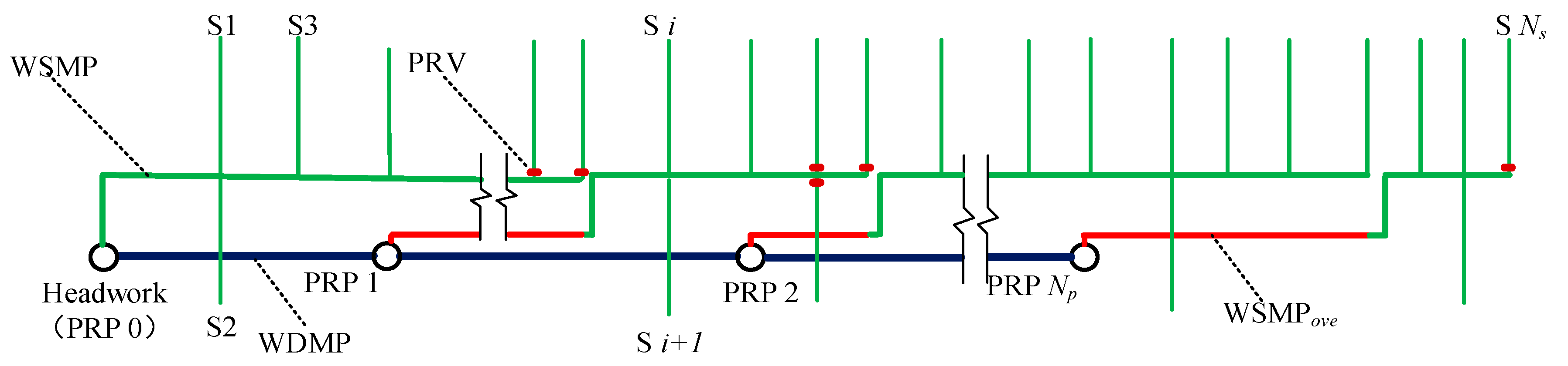
The G-MPS consists of WSMPs, WDMPs, PRPs, and PRVs (installed at the entrance of the submain pipes). A schematic of a G-MPS is displayed in Figure 1. The main pipe sections marked in green are WSMPs. The WSMP between two adjacent SMPs is regarded as a WSMP section. The function of a WSMP is to supply water to the SMPs controlled by it. The PRVs (marked in dull red) are installed at the entrance of the SMPs to reduce the pressure in the submain pipes, which are connected to the main pipe sections with high water pressure heads. The main pipe sections marked in blue are WDMPs. The function of a WDMP is to deliver water from the headwork to a PRP or from an upstream PRP to the following PRP. The function of a PRP (displayed in circles in Figure 1) is to reduce the excessive water head formed by long-distance water conveyance in relatively large terrain slopes to prevent the main pipelines from being damaged by high water pressure heads. The main pipe sections marked in red are the overlapping pipe sections of the WSMPs (WSMPove). No submain pipe is connected to these pipe sections. The function of the overlapping pipe sections is to form sufficient elevation differences by taking advantage of the terrain to provide the required pressure heads for the entrance of the subsequent SMPs. The SMPs from the headwork to the main pipe end location are numbered S1, S2, ..., and SNs. The PRPs from the headwork to the end location are numbered PRP 0, PRP 1, ..., and PRP Np. Among them, PRP 0 represents the water supply pond at the headwork.
The number and location of the PRPs are important factors affecting the pressure head of each main pipe section and the total cost of the G-MPS. If the number of PRPs is insufficient, excessive pressure heads are caused in some main pipe sections. In these sections, pipes with high-pressure bearing capacities must be used, which results in an increase in project costs. In contrast, a large number of PRPs causes insufficient pressure in some main pipe sections as well as excessive construction costs. Thus, a reasonable number and location of PRPs are the keys to ensuring pressure balance as well as reducing the total cost of the G-MPS. In addition, PRVs must be installed at the entrances of some submain pipes which are connected to the main pipe sections with high-pressure head, to reduce excessive pressure in order to ensure their safe operation. Therefore, how to scientifically and reasonably determine the optimal number and locations of PRPs and PRVs to reduce the total construction cost of a G-MPS and ensure its safe operation is worth studying.
2.2. Mathematical Models
The objective of this study was to minimize G-MPS construction costs while meeting the practicability and security requirements of the system. The objective functions and constraints are described in detail as follows.
2.2.1. Objective function
The optimization objective was to minimize the sum of the costs for the water supply pipes, water delivery pipes, PRPs, and PRVs. Although other parameters (soil movement for the trenches, auxiliary components, control valves, etc.) also impact the cost, the solutions obtained by taking these parameters into and out of the evaluation function (objective function) are basically consistent. Because the costs of these parameters basically have the same changing trend as the current objective function has. The objective function was defined as follows:
where F is the total cost (Yuan) of the subsystem; Ns and Nd are the numbers of WSMP and WDMP sections, respectively; Lsi and Csi are the length (m) and unit price (Yuan/m) of the WSMP section i, respectively; Ldj and Cdj are the length (m) and unit price (Yuan/m) of the WDMP section j, respectively; Np and Nv are the number of PRPs and PRVs, respectively; Cpk is the total cost (Yuan) of PRP k; Cvt is the unit price (Yuan) of PRV t. There are many factors involved in the total cost of a PRP (Cp). For the convenience of calculation of Cp, it is assumed that Cp is a function of the available water storage capacity of a PRP, . The calculation formula can be derived from fitting the relationship between total costs of PRPs and their water storage capacities of some constructed PRP cases.
2.2.2. Constraints
Constraints of pipe pressure bearing capacity: The maximum pressure of each pipe section must not exceed the bearing capacity of the adopted pipe.
where Pi,max is the maximum pressure (Mpa) of the pipe section i and Pi,c is the pressure bearing capacity (Mpa) of the pipe adopted for section i.
Constraints of the minimum pressure head at the entrance of the submain pipe: The pressure head at the inlet of the submain pipe must satisfy the following requirement:
where Hi is the pressure head (m) at the entrance of submain pipe i; Hreq is the required pressure head (m) at the entrance of submain pipe i; Nsub is the number of SMPs. Hi equals the elevation difference between the water demand node i (the entrance of the SMP i) and the PRP supplying water to the node i minus the total head loss (Hloss). The pressure at the entrance of the submain pipes was calculated and determined beginning with the working pressure of the emitters (dripper or sprinkler, etc.) in the irrigation field, from the downstream pipes to upstream pipes (in order of lateral, branch, submain pipes). With the known pressure requirement at the entrance of submain pipes, we guaranteed the minimum pressure head in the optimization process by solving the corresponding pressure constraints. In addition, PRVs were installed when the actual pressures exceed the upper limit.
The total head loss including frictional head loss and local head loss of a pipeline section was calculated using the following empirical formula:
where Hloss is the total head loss (m); is the expansion coefficient considering local head loss, whose value is generally 1.1; f is the coefficient of frictional head loss; l, Q, and D are the length (m), discharge (m3/h), and diameter (mm) of the pipe section, respectively; m and b are the coefficients associated with the pipe type. Note that the pipe diameter D in Equation (4) refers to the inner diameter and all hydraulic calculations involving pipe diameters in this study were calculated using the inner diameters.
Constraints of the maximum allowable current velocity: To prevent the deposition of impurity in pipeline water and to promote pipeline utilization efficiency, the current velocity should not be lower than a minimum value. In addition, to prevent a high current velocity from causing excessive wear and damage to the pipeline, the actual current velocity in each pipe section must not exceed a maximum allowable value. The minimum and maximum allowable current velocities were determined by engineering experience and hydraulic tests. The velocity values for different levels of water quality and different pipeline types were also different. The velocity constraint was expressed as follows:
where Vi is the actual current velocity (m/s) in pipe section i; Vmin and Vmax are the minimum and maximum allowable current velocities (m/s), respectively.
Diameter constraints: To ensure favorable hydraulic performance and operation safety of the irrigation pipeline, the diameter of a section of the WSMP or WDMP must be no less than that of the following section along the current direction. In this study, the diameter constraint was expressed as follows:
where Di is the inner diameter (mm) of pipe section i, Di + 1 is the inner diameter (mm) of pipe section i + 1, and N is the number of pipe sections.
2.3. Model Solving Method
In this study, a genetic algorithm based on a fixed proportion and direct comparison (GA-FPDC) served as the solving method. We mainly focused on how to scientifically select decision variables, encode and decode for GA-FPDC to develop an effective, efficient and general approach to address such problems.
2.3.1. GA-FPDC Method
GAs exhibit a stable performance and superior global search ability compared with most other heuristic algorithms and have received considerable attention and are widely used in various research fields [15,16,17,18]. Favorable results have been obtained with GAs in optimization problems [19,20,21,22,23,24,25,26,27]. In this study, the GA served as the optimization algorithm. The proposed model involve many constraints that must be managed. The general method of dealing with constraints in GAs involves using penalty function methods [28]. However, penalty function methods distort the characteristics of the objective function to a certain extent and have poor performance in handling highly constrained or nonconvex constrained optimization problems [29]. Thus, an improved genetic algorithm (GA), namely GA-FPDC, was adopted to deal with the model and its constraints.
The GA-FPDC tries to keep a fixed proportion of infeasible individuals in the population to increase the diversity of individuals in the population to prevent convergence to the local optimum and compares an individual’s superiority according to the stipulated rules of comparison. The details of the method are as follows:
First, according to Equation (7), we calculated the deviation value (vdev) that represents the degree to which each individual violates all the constraints (Equation (8)) in the model. If all the constraints were satisfied, the value of vdev was 0.
where vdev,i is the vdev value of individual i; Nine and Nequ are the numbers of inequalities and equalities, respectively; gj(x) is the inequality constraint; zk(x) is the equality constraint. NIND represents the number of individuals in a population of GAs.
Then, we calculated the proportion of infeasible individuals (Pinf) in the current population in the GA-FPDC procedure. We adjusted the acceptable vdev upper threshold (X) according to Equation (9). The fixed proportion (Pfix) in Equation (9) usually took a value of 0.2 under common conditions.
Finally, we used the following rules to select individuals in each GA selection operation. We randomly selected multiple pairs of individuals. For each pair, if both individuals were feasible, the individual with the best fitness value was selected; if both individuals were infeasible, the individual with the smaller vdev value was selected; if one individual was feasible while the other was infeasible, we determined whether the vdev of the infeasible individual was less than X. If its vdev was less than X, the individual with the best fitness value was selected; otherwise, the feasible individual was selected.
2.3.2. Decision Variables, Encoding, and Decoding Procedure
Decision Variables Selecting and Encoding
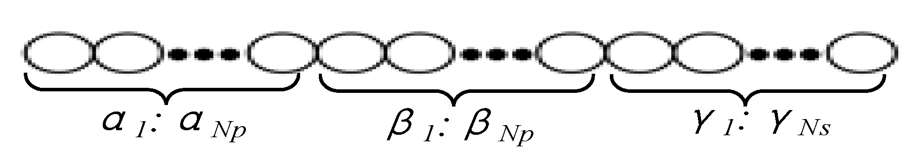
The decision variables directly affect the effectiveness, reliability and versatility of the algorithm. After analyzing and testing, three factors were considered as decision variables: the locations of PRPs, the main pipe end locations controlled by the corresponding PRPs, and the inner diameters of different main pipe sections, which were coded by three sub-chromosome, α1:αNp, β1:βNp, γ1:γNs (as shown in Figure 2).
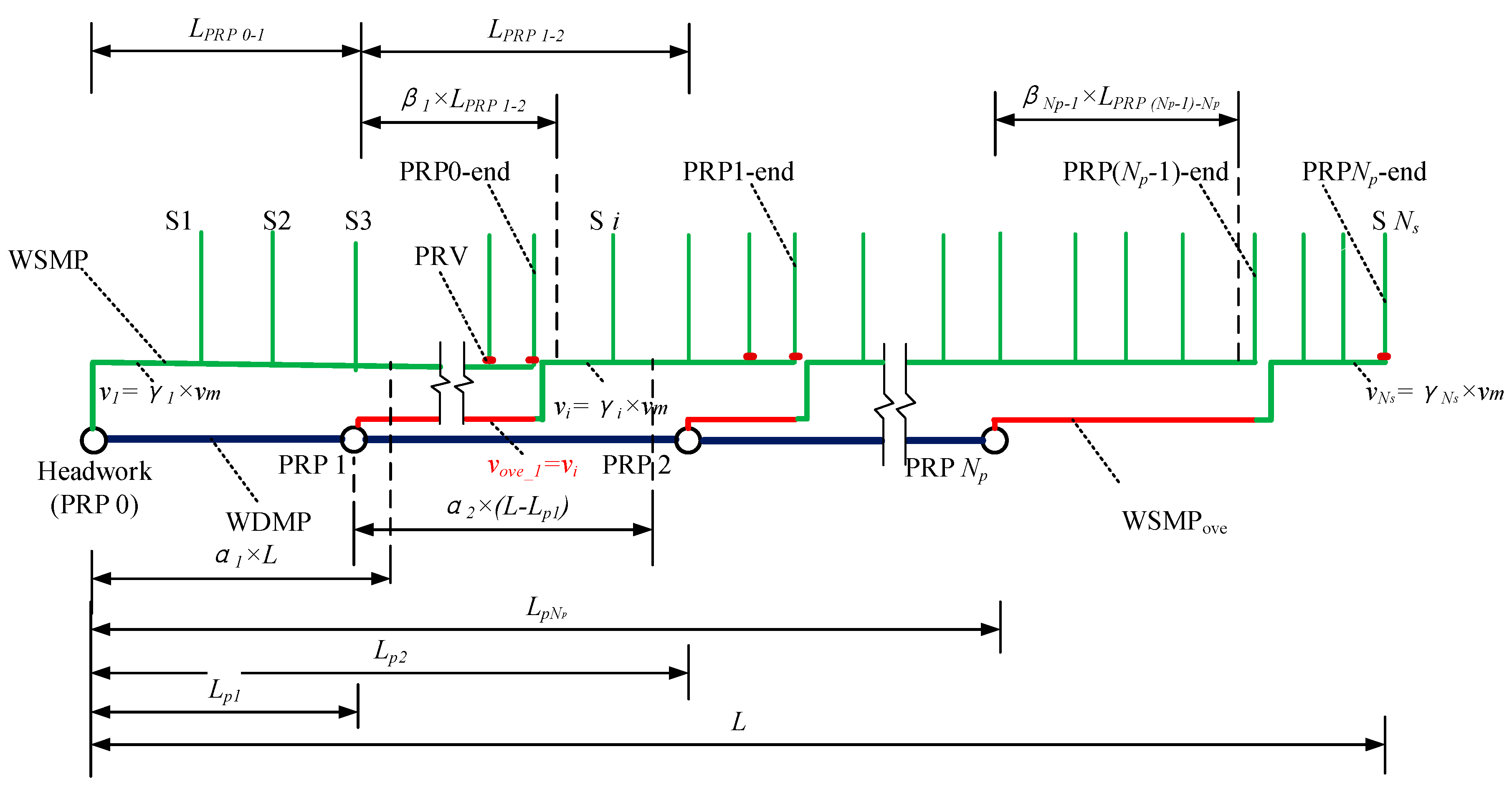
Decoding of the Locations of PRPs
The meanings of each sub-coding are illustrated in Figure 3. In order to simplify calculation and analysis, it was assumed that each PRP was only located at the position of each submain pipe entrance. The approximate location of PRP 1 can be determined by the value of α1 × L. Its actual position must be adjusted to the nearest submain pipe position according to the approximate position. Once the actual location of PRP 1 was determined, the distance (Lp1) between the headwork (PRP 0) and PRP 1 could be obtained, and the value of α1 needed to be updated by Lp1/L to improve the effectiveness of GA chromosome.
With a known Lp1, the approximate distance between PRP 2 and PRP 1 was determined by the value of α2 × (L − Lp1). Then, the approximate position of PRP 2 was obtained according to the location of PRP 1 and the value of α2 × (L − Lp1). The actual position of PRP 2 was determined by adjusting the approximate position to the nearest submain pipe position. Thus, the value of Lp2 could be determined, and the value of α2 needed to be updated by (Lp2 − Lp1)/L. According to the aforementioned method, the location of each PRP was determined. The values of αi were set from 0.3 and 0.7 in steps of 0.01 for practical use to avoid the locations of PRP to be too crowded or sparse.
Decoding of the Main Pipe end Location Controlled by Each PRP
Firstly, we determined the approximate main pipe end location controlled by the first PRP (PRP 0) by β1 × LPRP 1-2. Secondly, we adjusted its actual position to the nearest submain pipe position according to the approximate position to obtain the actual main pipe end location (PRP-0-end) controlled by PRP 0. Thirdly, we updated the value of β1 according to the position of PRP-0-end to improve the effectiveness of GA chromosome.
After determining the main pipe end location controlled by PRP 0, we calculated the approximate main pipe end location controlled by the second PRP (PRP 1) by β2 × LPRP 2-3. We Adjusted its actual position to the nearest submain pipe position according to the approximate position. We obtained the actual main pipe end location (PRP-1-end) controlled by PRP 1 and updated the value of β2 according to the position of the PRP-1-end. Using the aforementioned method, each actual main pipe end location controlled by PRP could be obtained. The values of βi were set from 0.3 and 0.7 in steps of 0.01 for practical use.
Decoding of Inner Diameters of Different Main Pipe Sections
The inner diameter (D) of each main pipe section (marked in green in Figure 3) was determined from the water velocity (v) and discharge (Q) of the section. Velocity v can be derived from code (γ) and the maximum allowable water velocity vm as follows: . The discharge (Q) of each main pipe section can be derived from the discharges of the submain pipes controlled by each PRP. The inner diameter (D) can be derived from the following equation: . The value of D needed to be adjusted to a commercially available diameter. Considering engineering practice, the values of γ ranged from 0.3 to 1.0 in steps of 0.01.
Note that the overlapping section (marked in red in Figure 3) of the main pipe had a discharge equal to that of the first water supply pipe section controlled by the corresponding PRP. Thus, the two sections had equal diameters. The inner diameter (D) of the water delivery pipe section (marked in blue in Figure 3) was determined from the pressure head difference between the two PRPs connected by it. Then, the value of D needed to be adjusted to a commercially available diameter.
2.3.3. Water Pressure Head Computing and Pipe Type for Different Main Pipe Sections Selecting
The pressure heads at each position of the main pipe and at the entrance of the submain pipe were calculated by the elevations of the PRP and the head loss of the pipe according to Equation (4). The pressure bear capacity of the pipe adopted was determined from the actual pressure head of the corresponding main pipe section.
Considering safety and economic factors, the WSMPs were made of unplasticized polyvinyl chloride (UPVC) (), fiber-reinforced plastic (FRP) (), and prestressed concrete cylinder (PCC) (). The WDMPs were made of prestressed reinforced concrete (PRC). To ensure the safety of the submain pipe, when the pressure at its entrance exceeded the maximum allowable pressure, a pressure reducing valve was installed.
3. Case Study
3.1. Basic Information of Two Cases
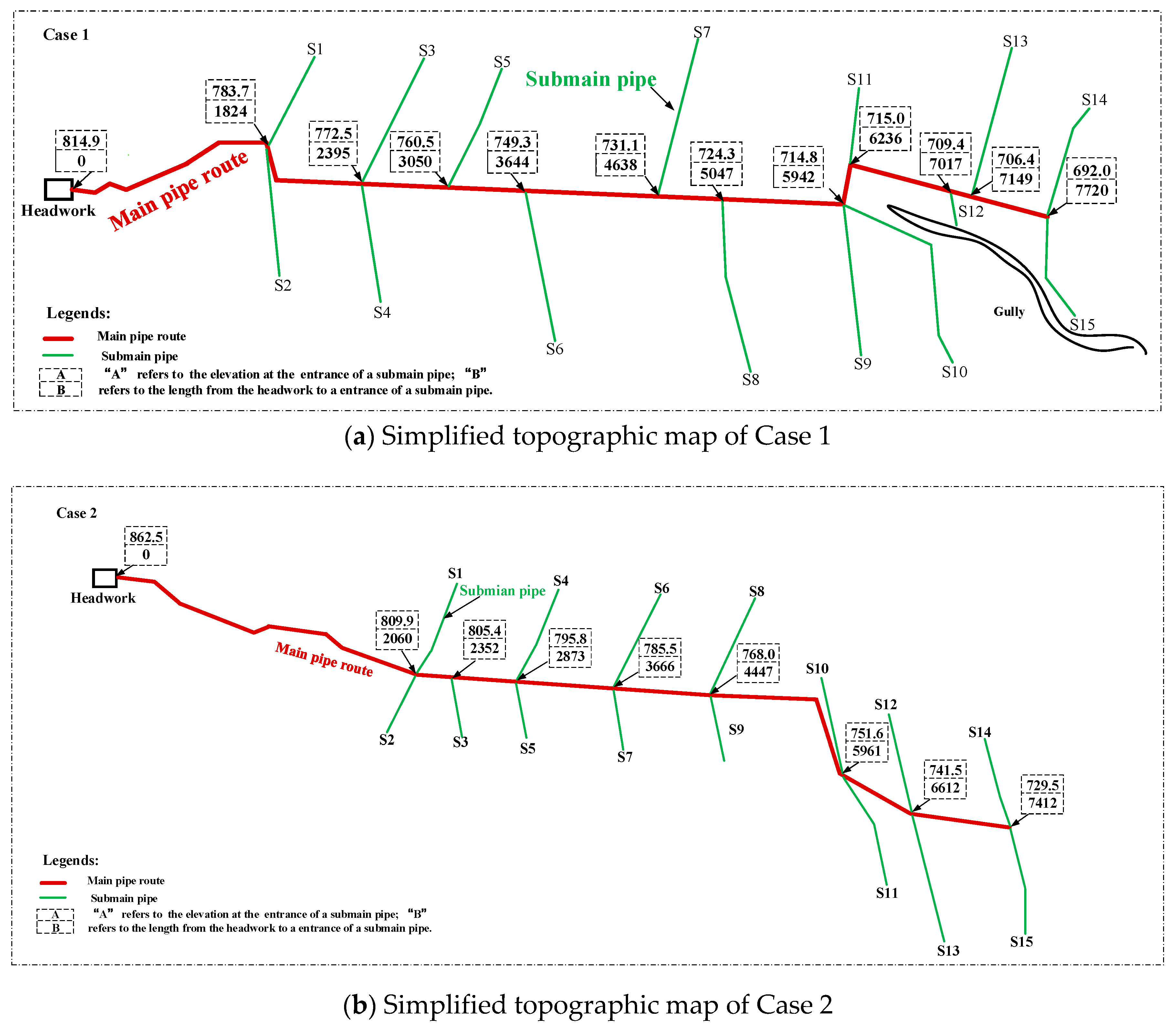
Two GDIPN systems were used to evaluate the performance of the model, which were located in Chabuchaer County, Xinjiang Uygur Autonomous Region. The simplified topographic maps of two GDIPN systems are depicted in Figure 4a (Case 1) and Figure 4b (Case 2), respectively. The required discharges for the submain pipes of the G-MPS are presented in Table 1. Table 2 presents the unit prices of different pipes. The commercially available sizes and unit prices of PRVs are presented in Table 3.
In this study, for the convenience of calculating the total cost of a PRP, we used an approximate calculation formula (Equation (10)), which was derived from analyzing collected data on the available water storage capacities (Vp) and total costs (Cp) of the PRPs of some existing projects in the researched area (as shown in Table 4).
where Cp is the total cost (Yuan) of a PRP and Vp is the available water storage capacity (m3) of the PRP. The available water storage capacity of a PRP (Vp) was equal to the total water requirement of the submain pipes under its control within 45 min. For example, if a PRP controled three submain pipes, of which the discharges were Qp1 m3/h, Qp2 m3/h, and Qp3 m3/h respectively, the available water storage capacity of the PRP (Vp) was calculated as follows:
3.2. Optimization Results and Analysis
The proposed GA-FPDC was used to optimize the aforementioned two cases. The population size of the GA-FPDC was set to 100, and the maximum generation was also set to 100. The crossover probability was set to 0.7, and the mutation probability was set to 0.01. In the calculation of head loss, the values of f, m, and b in Equation (4) for different pipe types were as follows: For UPVC and FRP pipes, the values of f, m, and b were 0.948 × 10⁵, 1.77, and 4.77, respectively. For PCC and PRC pipes, f was 1.516 × 10⁶, m was 2.00, and b was 5.33.
The number of PRPs was a controlling factor of the GA-FPDC automatic encoding. There should be an upper limit of the number of PRPs. Once the number exceeded this limit, the pressure head required by some water demand nodes was not met and there was no scheme with such number of PRPs that meets the requirements. In this study, the developed program based on GA-FPDC could not only allow users to specify the number of PRPs for calculation, but also automatically tried out the optimal scheme of different PRPs under the condition of meeting the requirements of pressure heads. The program terminated when the optimal scheme was obtained for the user-specified number of PRPs, or when the maximum number of PRPs was reached. In this study, we let the program run automatically. All feasible optimal design schemes with different number of PRPs for the G-MPS of Case 1 and Case 2 were obtained.
3.2.1. Optimization Results of Case 1
For Case 1, the upper limit number of PRPs constructed in the main pipe section was 3 according to the result of the program. The design scheme for Case 1 using the empirical method is illustrated in Figure 5a, whereas the optimal design schemes with different number of PRPs are illustrated in Figure 5b–d. The four sub-figures display the locations of the PRPs and the diameter of each main pipe section of the original design scheme and optimal design schemes with 1, 2, 3 PRPs for Case 1.
The total cost of the original design scheme of Case 1 was 4,418,061 Yuan, whereas the optimized cost obtained with the proposed method was 3,080,591 Yuan for the construction of one PRP (Scheme 1), 2,976,648 Yuan for the construction of two PRPs (Scheme 2), and 3,445,779 Yuan for the construction of three PRPs (Scheme 3). Compared with the total project cost of the original design scheme, the costs of the Scheme 1, Scheme 2, and Scheme 3 were reduced by 30.2%, 32.6%, and 22.0%, respectively. Among them, Scheme 2 achieved the greatest reduction in the total cost.
In addition, according to engineering experience, if the head pressure at the entrance of the submain pipe exceeds 30 m, a PRV must be installed for safety. The PRVs in Figure 5 are displayed in dull red. The scheme obtained by the empirical method shows that a total of nine PRVs were installed, indicating that the pressure heads at the entrance of nine submain pipes exceeded 30 m. Whereas Scheme 1, Scheme 2, and Scheme 3 needed to be equipped with seven, two, and three PRVs, respectively. It is obvious that Scheme 2 required fewer PRVs to be installed than those of the other schemes, which reveals that the pressure heads at the entrance of submain pipes of Scheme 2 were more reasonable and balanced. Therefore, the G-MPS of Case 1 designed according to Scheme 2 will be safer to operate and easier to manage.
3.2.2. Optimization Results of Case 2
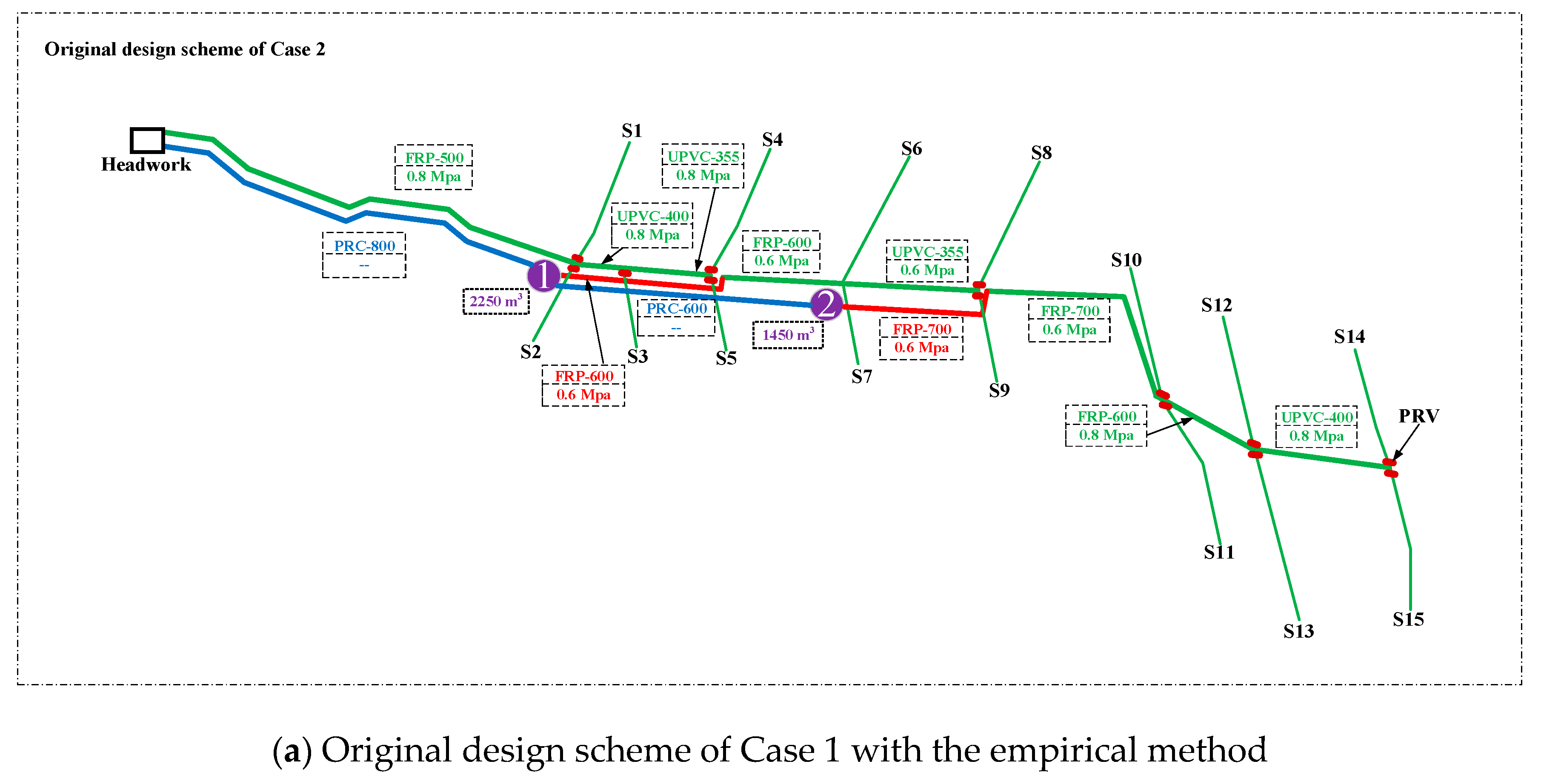
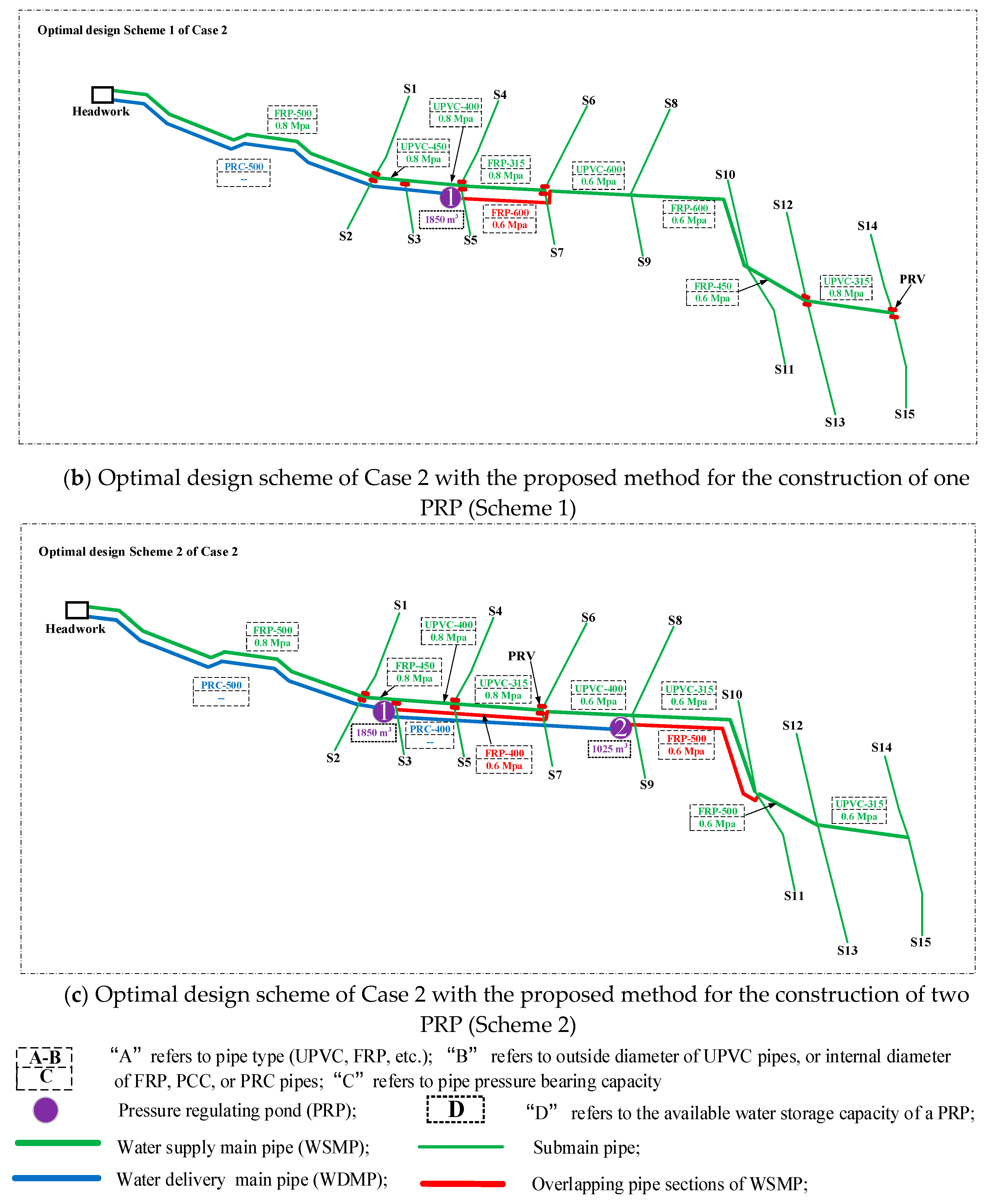
For Case 2, the upper limit number of PRPs was 3. The design schemes of Case 2 designed through the empirical method and the proposed method are illustrated in Figure 6.
The total cost of the original design scheme of Case 2 was 5,343,372 Yuan, whereas the optimized total cost obtained with the proposed method was 3,783,585 Yuan for the construction of one PRP (Scheme 1), 3,638,472 Yuan for the construction of two PRPs (Scheme 2). Compared with the project cost of the original design scheme, the costs of the Scheme 1 and Scheme 2 were reduced by 31.9% and 29.2%, respectively. The design scheme for the construction of two PRPs (Scheme 2) achieved the greatest reduction in the total cost among them. The numbers of PRVs of the original design scheme, Scheme 1, and Scheme 2 were 12, 11, and seven, respectively. Obviously, Scheme 2 was better than other schemes for Case 2.
3.2.3. Results Analysis and discussion
Whether for Case 1 or Case 2, the optimal design schemes obtained with the proposed method were the same as the number of PRPs necessary to be built in the original design schemes using the empirical method. However, both the total cost and the number of PRVs installed varied greatly comparing optimal design schemes with original design schemes. This is because of the influence of the locations of the PRPs. Due to the unreasonable location of the PRPs and the selection of pipe diameter in the original project scheme, the total cost increased significantly and the pressure heads of multiple pipe sections were over 30 m. As a result, pipes with a high-pressure bearing capacity must be used to adapt high-pressure head in the corresponding pipe sections, resulting in a significant increase in total cost. Besides, more PRVs were needed to reduce the pressure head for operation safety of submain pipes, which not only further increased project investment but also made it inconvenient to manage the GDIPN system.
Moreover, the optimal design schemes obtained with the proposed optimization method greatly reduced the total cost compared with that of the original schemes: the optimal schemes of Case 1 and Case 2 achieved a reduction of 32.6% and 31.9%, respectively. This indicates that the optimization of the number and locations of PRPs is of great significance in reducing project investment.
In this study, the water hammer problem in the operation process of a G-MPS was ignored. The study of water hammer has an impact on safe operation and management of the pipe system and it should be considered in a future study.
4. Conclusions
In this study, firstly, the general layout of G-MPS was generalized (Figure 1). Then a mathematical optimization model was constructed for the research and design of a G-MPS. The model was solved using the GA-FPDC method. Effective and scientific encoding and decoding methods were designed by considering the number and locations of the PRPs, the first and end submain pipes controlled by each PRP, and the inner diameter of each pipe section. In the process of optimization, many constraints were solved through scientific encoding and decoding as well as the FPDC method.
Two existing GDIPN systems were taken as typical cases for research. The results show that the design of the number and locations of PRPs had a considerable influence on the project cost. Moreover, reasonable locations of PRPs played a crucial role in balancing the pressure head in the G-MPS and bring convenience to project management.
Applying the proposed method to the design of a G-MPS in a GDIPN system can significantly reduce the design difficulty, simplify the design process, and improve the design efficiency. Moreover, using GA-FPDC as an optimization algorithm, a set of optimal design schemes can be obtained since every time of iteration of a GA-FPDC obtains a population composed of many individuals. Thus, designers can choose the most economical and reasonable one from many excellent schemes of the last population, combining design experience and engineering practice. It ensures the scientificity and rationality of the final design scheme to a great extent.
In a word, the presented method is an effective, efficient and easy-to-use tool to address optimization design of such GDIPN system problems. Using the method, designers can easily obtain a more reasonable and economic arrangement scheme of PRPs and PRVs by providing only some basic information regarding the irrigation area, such as elevations, discharges, and maximum and minimum allowable operating pressure at the entrances of the submain pipes.
Author Contributions
X.-Y.M., R.-H.Z. and Z.-H.Z. conceived and designed the research ideas. W.-Q.H. and Z.-K.L. contributed engineering design materials and engineering experience. R.-H.Z., Z.-H.Z., and X.-Y.M. established the mathematical optimization models and designed the solution algorithm. R.-H.Z., Z.-H.Z., and X.-Y.M. analyzed the data. R.-H.Z. wrote the paper. Z.-H.Z and X.-Y.M. revised the paper.
Funding
This research was funded by the National Science and Technology Support Program of China under grant 2015BAD24B02, the National Key R and D Program of China under grant 2017YFC0403202, and the Special Fund for Agro-scientific and Research in the Public Interest of China under grant 201503124.
Conflicts of Interest
The authors have no conflicts of interest to declare.
References
- Abadía, R.; Vera, J.; Rocamora, C.; Puerto, H. Generalisation of supply energy efficiency in irrigation distribution networks. Biosyst. Eng. 2018, 175, 146–155. [Google Scholar]
- Abadia, R.; Rocamora, C.; Ruiz, A.; Puerto, H. Energy efficiency in irrigation distribution networks I: Theory. Biosyst. Eng. 2008, 101, 21–27. [Google Scholar] [CrossRef]
- Abadia, R.; Rocamora, C.; Vera, J. Energy efficiency in irrigation distribution networks ii: Applications. Biosyst. Eng. 2012, 111, 398–411. [Google Scholar] [CrossRef]
- Córcoles, J.I.; Tarjuelo, J.M.; Moreno, M.A. Methodology to improve pumping station management of on-demand irrigation networks. Biosyst. Eng. 2016, 144, 94–104. [Google Scholar] [CrossRef]
- Fernández García, I.; Moreno, M.A.; Rodríguez Díaz, J.A. Optimum pumping station management for irrigation networks sectoring: Case of Bembezar MI (Spain). Agric. Water Manag. 2014, 144, 150–158. [Google Scholar] [CrossRef]
- Moreno, M.A.; Corcoles, J.I.; Tarjuelo, J.M.; Ortega, J.F. Energy efficiency of pressurized irrigation networks managed on-demand and under a rotation schedule. Biosyst. Eng. 2010, 107, 349–363. [Google Scholar] [CrossRef]
- Lamaddalena, N.; Khila, S. Efficiency-driven pumping station regulation in on-demand irrigation systems. Irrig. Sci. 2013, 31, 395–410. [Google Scholar] [CrossRef]
- Cabrera, E.; Gómez, E.; Espert, V.; Cabrera, E. Strategies to improve the energy efficiency of pressurized water systems. Procedia Eng. 2017, 186, 294–302. [Google Scholar] [CrossRef]
- Arai, Y.; Koizumi, A.; Inakazu, T.; Masuko, A.; Tamura, S. Optimized operation of water distribution system using multipurpose fuzzy LP model. Water Sci. Technol. Water Supply 2013, 13, 66–73. [Google Scholar] [CrossRef]
- Theocharis, M.E.; Tzimopoulos, C.D.; Sakellariou-Makrantonaki, M.A.; Yannopoulos, S.I.; Meletiou, I.K. Comparative calculation of irrigation networks using Labye’s method, the linear programming method and a simplified nonlinear method. Math. Comput. Model. 2010, 51, 286–299. [Google Scholar] [CrossRef]
- Da Conceição Cunha, M.; Sousa, J. Water distribution network design optimization: Simulated annealing approach. J. Water Resour. Plan. Manag. 1999, 125, 69–70. [Google Scholar]
- Simpson, A.; Dandy, G.; Murphy, L. Genetic algorithms compared to other techniques for pipe optimization. J. Water Resour. Plan. Manag. 1994, 120, 423–443. [Google Scholar] [CrossRef]
- Geem, Z.W.; Kim, J.H.; Loganathan, G.V. Harmony search optimization: Application to pipe network design. Int. J. Simul. Model. 2002, 22, 9. [Google Scholar] [CrossRef]
- Chung, G.; Lansey, K. Application of the shuffled frog leaping algorithm for the optimization of a general large-scale water supply system. Water Resour. Manag. 2008, 23, 797–823. [Google Scholar] [CrossRef]
- Goldberg, D.E. Genetic Algorithms in Search, Optimization & Machine Learning; Addison-Wesley: Boston, MA, USA, 1989. [Google Scholar]
- Zhao, R.; He, W.; Lou, Z.; Nie, W.; Ma, X. Synchronization optimization of pipeline layout and pipe diameter selection in a self-pressurized drip irrigation network system based on the genetic algorithm. Water 2019, 11, 489. [Google Scholar] [CrossRef]
- Babbar-Sebens, M.; Minsker, B.S. Interactive genetic algorithm with mixed initiative interaction for multi-criteria ground water monitoring design. Appl. Soft. Comput. 2018, 12, 182–195. [Google Scholar] [CrossRef]
- Bi, W.; Dandy, G.C.; Maier, H.R. Improved genetic algorithm optimization of water distribution system design by incorporating domain knowledge. Environ. Model. Softw. 2015, 69, 370–381. [Google Scholar] [CrossRef]
- Michalewicz, Z.; Janikow, C.Z.; Krawczyk, J.B. A modified genetic algorithm for optimal control problems. Comput. Math. Appl. 1992, 23, 83–94. [Google Scholar] [CrossRef] [Green Version]
- Ahn, C.W.; Ramakrishna, R.S. A genetic algorithm for shortest path routing problem and the sizing of populations. IEEE Trans. Evol. Comput. 2002, 6, 566–579. [Google Scholar]
- Lavric, V.; Iancu, P.; Plesu, V. Genetic algorithm optimisation of water consumption and wastewater network topology. J. Clean Prod. 2005, 13, 1405–1415. [Google Scholar] [CrossRef]
- Beltran, B.; Carrese, S.; Cipriani, E.; Petrelli, M. Transit network design with allocation of green vehicles: A genetic algorithm approach. Transp. Res. Part C Emerg. Technol. 2009, 17, 475–483. [Google Scholar] [CrossRef]
- Moradi, M.H.; Abedini, M. A combination of genetic algorithm and particle swarm optimization for optimal DG location and sizing in distribution systems. Int. J. Electr. Power Energy Syst. 2012, 34, 66–74. [Google Scholar] [CrossRef]
- Hartmann, S. A competitive genetic algorithm for resource-constrained project scheduling. Nav. Res. Logist. 2015, 45, 733–750. [Google Scholar] [CrossRef]
- Maity, S.; Roy, A.; Maiti, M. An imprecise multi-objective genetic algorithm for uncertain constrained multi-objective solid travelling salesman problem. Expert Syst. Appl. 2016, 46, 196–223. [Google Scholar] [CrossRef]
- Giassi, M.; Göteman, M. Layout design of wave energy parks by a genetic algorithm. Ocean Eng. 2018, 154, 252–261. [Google Scholar] [CrossRef]
- Mousavi, S.; Afghah, F.; Ashdown, J.D.; Turck, K. Use of a quantum genetic algorithm for coalition formation in large-scale UAV networks. Ad Hoc Netw. 2018, 87, 26–36. [Google Scholar] [CrossRef]
- Michalewicz, Z. Genetic algorithms + data structures = evolution programs. Comput. Stat. Data Anal. 1996, 24, 372–373. [Google Scholar]
- Deb, K. An efficient constraint handling method for genetic algorithms. Comput. Meth. Appl. Mech. Eng. 2002, 186, 311–338. [Google Scholar] [CrossRef]
Figure 1.
Schematic of a G-MPS.

Figure 2.
The chromosome.

Figure 3.
Diagram of the problem generalization.

Figure 4.
Simplified topographic maps of Case 1 and Case 2.

Figure 5.
Design schemes with the (a) empirical method and (b–d) proposed methods for Case 1.


Figure 6.
Design schemes with the (a) empirical method and (b,c) proposed methods for Case 2.


Table 1.
Required discharges (Qreq) of the submain pipes.
| No. of SMP | S1 | S2 | S3 | S4 | S5 | S6 | S7 | S8 | S9 | S10 | S11 | S12 | S13 | S14 | S15 |
|---|---|---|---|---|---|---|---|---|---|---|---|---|---|---|---|
| Case 1 Qreq (m3/h) | 102.4 | 102.4 | 102.4 | 204.8 | 204.8 | 307.2 | 409.6 | 102.4 | 204.8 | 204.8 | 102.4 | 102.4 | 204.8 | 204.8 | 204.8 |
| Case 2 Qreq (m3/h) | 204.8 | 102.4 | 102.4 | 204.8 | 204.8 | 204.8 | 204.8 | 204.8 | 204.8 | 204.8 | 204.8 | 204.8 | 307.2 | 307.2 | 204.8 |
Table 2.
Unit prices (Yuan/m) of different pipes.
| Pipe Pressure Bearing Capacity | Unplasticized Polyvinyl Chloride (UPVC) Pipes | ||||||||||
| Outside Diameter (mm) | 125 | 140 | 160 | 180 | 200 | 225 | 250 | 315 | 355 | 400 | |
| 0.6 Mpa | Pipe thickness (mm) | 3.1 | 3.5 | 4 | 4.4 | 4.9 | 5.5 | 6.2 | 7.7 | 8.7 | 9.8 |
| Internal diameter (mm) | 118.8 | 133 | 152 | 171.2 | 190.2 | 214 | 237.6 | 299.6 | 337.6 | 380.4 | |
| Unit price (Yuan/m) | 16.4 | 20.3 | 26.6 | 32.5 | 40.4 | 51 | 63.6 | 99.2 | 114 | 144.2 | |
| 0.8 Mpa | Pipe thickness (mm) | 3.9 | 4.3 | 4.9 | 5.5 | 6.2 | 6.9 | 7.7 | 9.7 | 10.9 | 12.3 |
| Internal diameter (mm) | 117.2 | 131.4 | 150.2 | 169 | 187.6 | 211.2 | 234.6 | 295.6 | 333.2 | 375.4 | |
| Unit price (Yuan/m) | 19.8 | 24.6 | 32 | 40.4 | 50.6 | 63.2 | 78.1 | 123.9 | 157.1 | 199.5 | |
| Pipe Pressure Bearing Capacity | Fiber-Reinforced Plastic (FRP) Pipes | ||||||||||
| Internal Diameter (mm) | 450 | 500 | 600 | 700 | 800 | ||||||
| 0.6 Mpa | Pipe thickness (mm) | 8.5 | 9.1 | 10.6 | 12.5 | 14.8 | |||||
| Outside diameter (mm) | 467 | 518.2 | 621.2 | 725 | 829.6 | ||||||
| Unit price (Yuan/m) | 289 | 320 | 460 | 556 | 730 | ||||||
| 0.8 Mpa | Pipe thickness (mm) | 10.1 | 11.3 | 12.8 | 14.6 | 16.9 | |||||
| Outside diameter (mm) | 470.2 | 522.6 | 625.6 | 729.2 | 833.8 | ||||||
| Unit price (Yuan/m) | 289 | 330 | 470 | 596 | 750 | ||||||
| Pipe Pressure Bearing Capacity | Prestressed Concrete Cylinder (PCC) Pipes | ||||||||||
| Internal Diameter (mm) | 1000 | 1200 | 1400 | 1600 | 1800 | ||||||
| 1.0 Mpa | Pipe thickness (mm) | 81.5 | 91.5 | 111.5 | 121.5 | 136.5 | |||||
| Outside diameter (mm) | 1163 | 1383 | 1623 | 1843 | 2073 | ||||||
| Unit price (Yuan/m) | 995 | 1320 | 1550 | 1850 | 2150 | ||||||
| Pipe Pressure Bearing Capacity | Prestressed reinforced concrete (PRC) pipes | ||||||||||
| Internal Diameter (mm) | 300 | 400 | 500 | 600 | 700 | 800 | 1000 | 1200 | |||
| -- | Pipe thickness (mm) | 45 | 50 | 50 | 55 | 55 | 60 | 70 | 80 | ||
| Outside diameter (mm) | 390 | 500 | 600 | 710 | 810 | 920 | 1140 | 1360 | |||
| Unit price (Yuan/m) | 40 | 55 | 170 | 260 | 295 | 325 | 475 | 575 | |||
Table 3.
Sizes and unit prices of diaphragm pressure relief valves.
| Size (mm) | 150 | 200 | 250 | 300 | 350 | 400 |
|---|---|---|---|---|---|---|
| Unit price (Yuan/each) | 28,000 | 34,120 | 42,890 | 54,300 | 68,360 | 85,060 |
Table 4.
Water storage capacities and total costs of different PRPs.
| Available Water Storage Capacity (m3) | 600 | 1125 | 1750 | 2250 |
|---|---|---|---|---|
| Total cost (Yuan) | 191,000 | 325,800 | 441,800 | 558,500 |
© 2019 by the authors. Licensee MDPI, Basel, Switzerland. This article is an open access article distributed under the terms and conditions of the Creative Commons Attribution (CC BY) license (http://creativecommons.org/licenses/by/4.0/).
Share and Cite
MDPI and ACS Style
Zhao, R.-H.; Zhang, Z.-H.; He, W.-Q.; Lou, Z.-K.; Ma, X.-Y. Synthetical Optimization of a Gravity-Driven Irrigation Pipeline Network System with Pressure-Regulating Facilities. Water 2019, 11, 1112. https://doi.org/10.3390/w11051112
AMA Style
Zhao R-H, Zhang Z-H, He W-Q, Lou Z-K, Ma X-Y. Synthetical Optimization of a Gravity-Driven Irrigation Pipeline Network System with Pressure-Regulating Facilities. Water. 2019; 11(5):1112. https://doi.org/10.3390/w11051112
Chicago/Turabian StyleZhao, Rong-Heng, Zi-Han Zhang, Wu-Quan He, Zong-Ke Lou, and Xiao-Yi Ma. 2019. "Synthetical Optimization of a Gravity-Driven Irrigation Pipeline Network System with Pressure-Regulating Facilities" Water 11, no. 5: 1112. https://doi.org/10.3390/w11051112
Note that from the first issue of 2016, this journal uses article numbers instead of page numbers. See further details here.