New ESP8285 based 1Channel Inching/Locking 5V/12V Sonoff #453
Comments
|
Hi, |
|
This Device: https://www.itead.cc/smart-home/inching-self-locking-wifi-wireless-switch.html |
|
Yes albeit not the same as in the 1 channel device photo. That indicates an ESP8266 unit. Mone is ESP8285 based. |
|
The sonoff touch of mine is based on the PSF-A01 itead ESP8285 module. |
|
Some pics: |


|
OK - so I have managed to flash the unit with Arduino IDE on latest Tasmota. I can access the web interface after restart, but the device now shows odd behaviour. When in locking mode the device acts normally as a switch, but when in inching mode and the device is either trigger by button press or web toggle it goes into a 10 second flip flop (switching on and off repeatedly) and then hangs. After a restart the device is frozen still and I have to re-flash firmware to get it active again. I have tried multiple device selections in the device setup (Basic, Slampher, 1 Channel and both 4 channel options.) My assumption is that the "on" command trigger a gpio either high or low and that the external inching function sends a signal back to the ESP8285 to switch off the trigger gpio. With the new firmware this does not happen and as such the device "loops" and eventually somehow corrupts the ESP8285. Open to any ideas? |
|
tasmota has never supported the inching functionality of this board.
k
|
|
Hello everybody! |
|
Hi, |
|
Using Arduino (Ground to RST): on the PSFB01 you need to pull GPIO2 to Ground before Powerup and afterwards connect RX TX // TX RX using your Arduino. In my case there was no pinout on the PCB whatsoever, so I had to solder it directly on the PSFB01 |
|
I can only assume this device is probably the latest effort from Itead to try and stop us from using custom firmware. the relay is seem to be driven by the stc15w204s. |
|
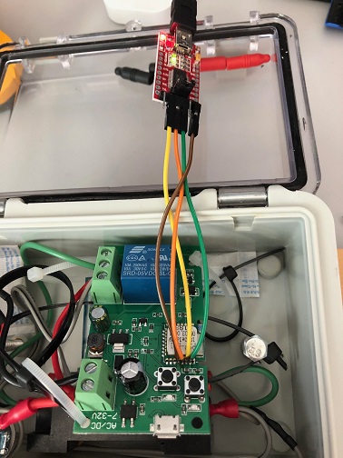
I was able to get this sort of working... (See attached picture) I had to remove 1 IC to stop the bouncing of the relay and bridge 2 of the empty pads. Also, need to add a pull-up resistor as indicated in the pic to make the button work after removing the IC.
|

|
Brilliant stuff. Didn't think about that. Will try that and see if it helps. |
|
The devices discussed in this issue are based on the esp8285 chip while the original device used the esp8266 chip. The main difference is the way flash is addressed and loading the default sonoff firmware on these devices will probably NOT work unless you take the following steps:
|
|
Mine is definitely esp8285. That is the one I compiled and loaded on mine. I believe I tried the 1 channel and the behavior was not perfect. In my case, I noted that when using the inching method, it would work perfectly as expected but with one issue. I could turn on or off generally about 5 times in row. Thereafter, the next 2 or 3 attempts would not have effect. |
|
levonbragg, do you still have the IC number for the chip you removed. |
|
zizebra, I do not. All of mine are blank. Looks like they were rubbed off. |
|
Hope itead is not trying to revive the useless ESP8266 Black board T5 |
|
arendst, |
|
arendst, on my end there is no joy. I still see the behavior where some commands will have no effect. it usually takes up to 4 commands to get a response. thereafter the next 4-5 commands works before it stops responding again. below is a trace from webconsole. the highlighted power on commands did not work
|

|
@zizebra you have a MQTT server problem. This causes delays in command processing. If you fail to connect the MQTT server execute command mqttretry 60 to make more room for command processing. |
|
thank you., I didn't think that to be the problem. My sd card for my PI packed up before I received this device. I will re-install the mqtt server and test |
|
I manage to reinstall my PI yesterday. However could not test, because my sonoff kept trying to connect to the mqtt server provided in the code instead of my custom one. It will usually connect to the correct one after a couple of hours. I hope to have a good test later on. |
|
Finally managed to test. It is definitely working perfectly with mqtt. One minor issue which I picked up is that after loading firmware, the relay default is activated. When I choose 1ch on configuration. The relay is changed to default off. Occasionally when the sonoff restarts, the relay is activated momentarily before being Switch off. Does any one have a quick workaround for this. I would like the relay start default off throughout the reboots. |
5.3.0 20170715
* Major Hue rewrite which might introduce Alexa problems. If so,
initiate an issue
* Add support for Sonoff Led and BN-SZ01 Ceiling Led brightness control
to Hue
* Fix Sonoff Led Power, Dimmer and Color MQTT response (#176)
* Add commands Delay and Backlog to allow multiple commands at once
separated by ";" (#593)
* Use default flashmode DOUT to solve restart hangs on esp8285 chips
(#453, #598)
* Change Web console column width from 99 to 300 (#599)
|
You can simply use this wiring (if you have someone to help you, you dont neet so solder). |

|
hello jktz90, please if I connect my usb to uart like this it does overheat very fast, so instead I am powering the sonoff from his own usb and connecting tx rx and Ground of module to my usb to uart but I get eeprom error, I also not sure that ESP goes into Flash mode (i assume rx pin is #5 from bottom on the image and I assume the connect to ground is the second pin from left on the bottom row of connectors. Your help greatly appreciated |
|
You probably plugged Ground/3V the wrong way around. You can definitely use your adapter to power the Sonoff. Before you power up the Sonoff, you have to pull the pin out in the bottom to Ground (I don't have the official datasheet anymore) in order to force flash mode (I can't remember how exactly but the LED blinked differently to indicate the flash mode). |
|
3v is the square pin one (blue wire on your pic) isn it? please what pin on your pic has to go to ground to enable flash |
|
Check the wiki FAQ entry on ghosting. Please address your questions to the Tasmota Support Discord Chat. The chat is a better and more dynamic channel for helping you. Github issues are best used for Tasmota software feature requests and bug reporting. Troubleshooting and setup assistance is more effective using an interactive forum. Please check the Contributing Guideline and Policy and the Support Guide. Thanks. Support InformationSee Wiki for more information. |
|
I wanted to reopen this (it can be immediately reclosed) JUST because I know of no other place to post this valuable information, and in my pursuit of the information I found no other place online where it is properly discussed!! Here is how to flash your PSF-B01. Use this pinout; Use this flash boot method (press both buttons while powering it. Both LEDs need to come on. You can flash Tasmota now. Once booted, set it to module "1 channel (12)" in the included module list (no external template is needed). VERY IMPORTANT This will disable the "triple press" functionality that usually reboots ESP8266 into SmartConfig Mode. After that, you can select via the hardware button if you want inching or locking latch, and you are good to go! I hope this message saves someone A LOT of time. I took me quite a while to figure out why the module was going haywire. |

|
Seems like i have another new layout ... Tried several things to enter Flash Mode, without luck:
Does someone have an idea? |
I have same board aslo.. did you find a way to flash it? |
thank you SOOOOO much for "SetOption13 1" fixed my all problems |
|
Hello I plan to add an external antenna for the attached board. Does anyone know where to solder the external antenna lead? |

|
A picture of the bottom may help.
El jue., 16 jul. 2020 a las 10:59, Emile7 (<notifications@github.com>)
escribió:
… Hello I plan to add an external antenna for the attached board. Does
anyone know where to solder the external antenna lead?
[image: 7c09ea96-3a7b-11e7-8498-f53947794f2f]
<https://user-images.githubusercontent.com/68385687/87679715-2d21f780-c785-11ea-8fc6-cecaa6870bf5.jpg>
—
You are receiving this because you are subscribed to this thread.
Reply to this email directly, view it on GitHub
<#453 (comment)>,
or unsubscribe
<https://github.com/notifications/unsubscribe-auth/ACXBW4PGZE4XKGB54G2KF7LR34BS7ANCNFSM4DLN6EFA>
.
|
|

|
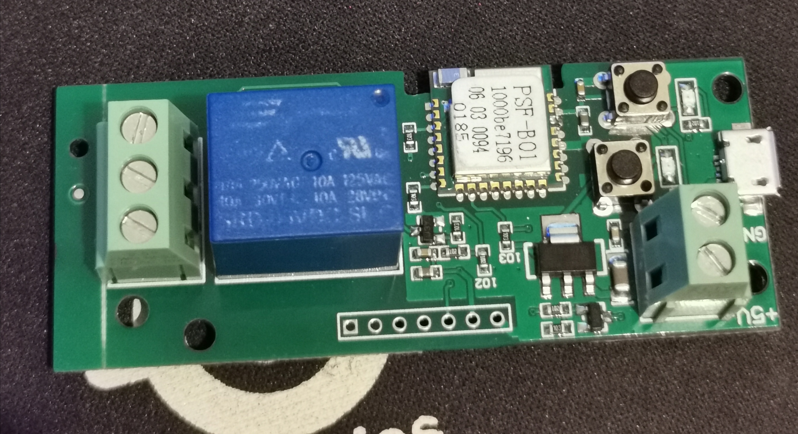
That module has a ceramic antena, the white component in the corner.
You may need to remove it in order to attach a different one.
Youcan connect also connect on module pin 1.
El El vie, 17 de jul. de 2020 a la(s) 01:17, Emile7 <
notifications@github.com> escribió:
… A picture of the bottom may help. El jue., 16 jul. 2020 a las 10:59,
Emile7 ***@***.***) escribió:
… <#m_7834619719896913155_m_8465963238316833967_>
Hello I plan to add an external antenna for the attached board. Does
anyone know where to solder the external antenna lead? [image:
7c09ea96-3a7b-11e7-8498-f53947794f2f]
https://user-images.githubusercontent.com/68385687/87679715-2d21f780-c785-11ea-8fc6-cecaa6870bf5.jpg
— You are receiving this because you are subscribed to this thread. Reply
to this email directly, view it on GitHub <#453 (comment)
<#453 (comment)>>,
or unsubscribe
https://github.com/notifications/unsubscribe-auth/ACXBW4PGZE4XKGB54G2KF7LR34BS7ANCNFSM4DLN6EFA
.
[image: back]
<https://user-images.githubusercontent.com/68385687/87748007-76ae2900-c7fd-11ea-9cce-c9b5c07f2444.jpeg>
—
You are receiving this because you commented.
Reply to this email directly, view it on GitHub
<#453 (comment)>,
or unsubscribe
<https://github.com/notifications/unsubscribe-auth/ACXBW4IY2SWXXL4FNDVTE7DR37GD5ANCNFSM4DLN6EFA>
.
|
You mean connect to pin1 without removing the ceramic antenna? |
|
No, that will produce an impedance mismatching. Antenas are tricky to adapt.
Yor external one may be different impedance than the ceramic one. You will
need to adjust with a LC netwok.
El El vie, 17 de jul. de 2020 a la(s) 13:31, Emile7 <
notifications@github.com> escribió:
… That module has a ceramic antena, the white component in the corner. You
may need to remove it in order to attach a different one. Youcan connect
also connect on module pin 1. El El vie, 17 de jul. de 2020 a la(s) 01:17,
Emile7 < ***@***.***> escribió:
… <#m_7700677667163616990_>
A picture of the bottom may help. El jue., 16 jul. 2020 a las 10:59,
Emile7 *@*.***) escribió: …
<#m_7834619719896913155_m_8465963238316833967_> Hello I plan to add an
external antenna for the attached board. Does anyone know where to solder
the external antenna lead? [image: 7c09ea96-3a7b-11e7-8498-f53947794f2f]
https://user-images.githubusercontent.com/68385687/87679715-2d21f780-c785-11ea-8fc6-cecaa6870bf5.jpg
— You are receiving this because you are subscribed to this thread. Reply
to this email directly, view it on GitHub <#453
<#453> (comment) <#453 (comment)
<#453 (comment)>>>,
or unsubscribe
https://github.com/notifications/unsubscribe-auth/ACXBW4PGZE4XKGB54G2KF7LR34BS7ANCNFSM4DLN6EFA
. [image: back]
https://user-images.githubusercontent.com/68385687/87748007-76ae2900-c7fd-11ea-9cce-c9b5c07f2444.jpeg
— You are receiving this because you commented. Reply to this email
directly, view it on GitHub <#453 (comment)
<#453 (comment)>>,
or unsubscribe
https://github.com/notifications/unsubscribe-auth/ACXBW4IY2SWXXL4FNDVTE7DR37GD5ANCNFSM4DLN6EFA
.
You mean connect to pin1 without removing the ceramic antenna?
—
You are receiving this because you commented.
Reply to this email directly, view it on GitHub
<#453 (comment)>,
or unsubscribe
<https://github.com/notifications/unsubscribe-auth/ACXBW4NNSUAHEGCTRIB3SILR4B4G5ANCNFSM4DLN6EFA>
.
|
Thanks ryaske for the information on that version of the board. PS. I've had a look at the datasheet for the ESP8285 and it shows both pins 14 and 26 as Tx during flash programming and pin 25 as Rx during flash programming which is different to what you show. |
Same, can't find much on this version. |
I'll admit, these boards are a pain to flash because you have to connect directly to the chip, but there's a bunch of info on this board, pictures and all in this very thread...? I just flashed 4 of them this week using info mostly from here... As far as getting it into flashing mode, that's actually quite easy once you know what to do: Simply hold down BOTH buttons as you power up the device. If you hold the buttons down long enough (about 3-5 sec), when you release them the board will automatically be in flashing mode. You can tell the board is ready to be flashed if the red LED next to the blue relay & the LED next to the button closer to the edge of the board are on steady/solid red. If you don’t hold the buttons down long enough or immediately release them after powering the board up, the relay will toggle on & off repeatedly and the LED will slowly flash matching the state of the relay. In this case simply press the button closer to the edge of the circuit board once & it will put the board into flash mode. Here’s a quick YouTube video (not mine) showing how to easily get the board into flashing mode. Now actually getting a successful flash once it's in flashing mode can still be a royal pain in my experience if you're just hand holding pins to the chip. I literally had to make around 30 attempts on one of the boards I flashed. The Tasmotizer software simply wasn't detecting the board so wouldn't start flashing. Not sure what the problem was as 2 of the others I flashed worked first try. After you've got the board flashed you can get it working properly in Tasmota by simply going to Configure Module & selecting Module: 1 Channel (12) There's no need to configure a template as best I can tell so I haven't tested it, but if you do want to configure a template (instead of using the Module method) then here's the template you should probably check out: 1 Channel Inching/Self-Locking Relay (Even though the pictures are different this should be the same device. You'll notice at the bottom they link to the same video I did above.) The last important thing about this device that I've discovered but have not seen well documented is that even after you've got Tasmota loaded, the mode button (closer to the edge of the device) still toggles the device between a hardware based inching vs self-locking mode. Importantly, if you want to use the Tasmota "PulseTime" command (basically a software controlled inching mode) it appears the device MUST be in self-locking mode. (The LED by the mode button should be ON.) Hope that helps. |
Hey KBrown, If you follow the thread you will see there appears to be two different versions of this board. The one quoted here from OP does not contain the 4 pins as shown in the image below.
This is the board he was talking about, and the board I have. There is no 3v pin. |

You're right, I did overlook that detail, sorry! But even so... As long as the main chip hasn't changed (which it doesn't look like it has) I wouldn't expect the flashing procedure to change any... You shouldn't need any of those holes. I didn't use any of them for flashing. |
hi! i am in same situation, i have de same board. |
Not that I am aware of. I ended up returning mine to Amazon and getting a D1 Mini with Relay Shield, I actually got 2 for the same price as this board. Plugged in via USB and flashed with Tasmota, so much easier than trying to mess with this board. |
|
Ppl. Its possible flash this esp, i cant find tje layout scheme... thnkx
|

|
yes, it is. Look above posts |
Mine doenst.t have the little holes to gbd and 3.3v if you see |
|
Anyone tried to connect ds18b20 (or any other) temperature sensor to this board? Looks like no GPIOx is connected to the pins so only way is to connect straight into ESP? Which pin, any suggestions? |

|
The WiFi module is actually an ESP8285 SMT Module
|

|
I think it is an ESP-M1 |

My board looks like yours too. I managed to flash it by soldering 4 wires to the contacts on the little board PSF-B01 board. The pinouts from here helped: Soldering the 4 small contacts in a row was a bit tricky, but it worked nicely.
|
There is no need to mess with the board,
|
Hello, I managed to put tasmota in this model following this pinout and to put it in flash mode I held both buttons before inserting the converter, and after that I kept pressing it for 5s. I Hope It helps.
|


|
Yet another board (Includes RF also)
|


This helped me a lot. Thank you, @masterkey26. |


Hi All,
I just took possession of the above new device that appears to be the new version of the old device - the pics on the Itead website has not even been updated.
This board is based on the PSF-B01 itead ESP8285 module.
I have not found any custom firmware yet that appears to work - not Tasmota, ESPEasy or Espurna seems to work.
Using Tasmota it uploads fine with success flag - but this basically puts the module in an endless switch loop with no connection to wifi as setup in config file.
Anyone have any info?
Regards,
Ed
The text was updated successfully, but these errors were encountered: