Study on the Best Depth of Stilling Basin with Shallow-Water Cushion

1
State Key Laboratory of Hydraulics and Mountain River Development and Protection, College of Water Resource and Hydropower, Sichuan University, Chengdu 610065, Sichuan, China
2
Department Civil and Environmental Engineering, Michigan State University, East Lansing, MI 48824, USA
*
Author to whom correspondence should be addressed.
Water 2018, 10(12), 1801; https://doi.org/10.3390/w10121801
Submission received: 7 November 2018
/
Revised: 28 November 2018
/
Accepted: 4 December 2018
/
Published: 7 December 2018
(This article belongs to the Special Issue Advances in Hydraulics and Hydroinformatics)
Abstract
:The depth of the stilling basin with shallow-water cushion (SBSWC) is a key factor that affects the flow regime of hydraulic jump in the basin. However, the specific depth at which the water cushion is considered as ‘shallow’ has not been stated clearly by far, and only conceptual description is provided. Therefore, in order to define the best depth of SBSWC and its relationship between the Froude number at the inlet of the stilling basin, a large number of experiments were carried out to investigate SBSWC. First of all, 30 cases including five different Froude numbers and six depths were selected for which large eddy simulation (LES) was firstly verified by the experiments and then adopted to calculate the hydraulic characteristics in the stilling basin. Finally, three standards, based on the flow regime of hydraulic jump, the location of the main stream and the energy dissipation rate, were proposed to define the best depth of SBSWC. The three criteria are as follows: (1) a complete hydraulic jump occurs in the basin (2) the water cushion is about 1/10–1/3 deep of the stilling basin, and (3) the energy dissipation rate is more than 70% and the unit volume energy dissipation rate is as high as possible. It showed that the best depth ratio of SBSWC (depth to length ratio) was between 0.1 and 0.3 and it also indicated the best depth increased with the increase in Froude number. The results of the work are of significance to the design and optimizing of SBSWC.
1. Introduction
At present, the energy dissipation by hydraulic jump is used for downstream in many hydraulic projects [1], of which the stilling basin plays an important role in energy dissipation. However, the traditional stilling basin has disadvantages such as high underflow speed near the bottom [2,3,4], apparent damages by erosion and cavitation as well as insufficient energy dissipation rate [5]. Many researchers have made studies on such problems. The concept of a stilling basin with shallow-water cushion (SBSWC) was introduced [6]; namely, a shallow-water cushion is added to the ordinary stilling basin. In the structure of the new type stilling basin, the water cushion formed at the basin bottom can be used as the ‘flexible bottom plate’, which applies a flexible counterforce to the water stream in the steep slope section and ‘absorbs’ impact force of high speed flow on the floor of the stilling basin, so as to protect the bottom of the basin. After that, a series of studies on the impacts caused by inlet type, inflow angle, and low Froude number of the stilling basin with shallow-water cushion on its hydraulic characteristics were conducted [7]. For example, the concept of a stilling basin with double shallow-water cushions is an extension of SBSWC, which has the same advantages as SBSWC, but with better hydraulic characteristics [8], lower underflow speed, and better distribution of dynamic pressures of bottom plate of the stilling basin. The stilling basin with a drop sill is similar to SBSWC in shape [9,10,11,12,13,14]. However, the former one is focused on the connection type of a drop sill at the stilling basin inlet, while the latter one is focused on the energy dissipation mechanism of the stilling basin and the effect of the shallow-water cushion.
The depth of SBSWC is of critical importance to the energy dissipation effect of the stilling basin; however, no systematic study has been made on it for now. Besides, whether the water cushion is considered as deep or shallow has not been defined clearly since the concept of SBSWC was proposed. This paper attempt to propose an accurate and practical definition of the best depth of SBSWC in terms of three aspects; namely, flow regime, main stream location, and energy dissipation rate. If the water cushion depth is higher than the best depth, it is not necessary; if the water cushion depth whereas is lower than the best depth, the water cushion cannot play the role of the buffer action fully. Therefore, it is expected that in a stilling basin with the best depth, a complete hydraulic jump (critical hydraulic jump and submerged hydraulic jump are considered complete hydraulic jumps) occurs and the main stream is not located too close or far from the bottom of the basin, and the energy dissipation rate is as high as possible.
This study was not about the thickness of a shallow water cushion, but to study the depths of a stilling basin with shallow-water cushion required at different Froude numbers. In order to obtain the best stilling basin depth (represented by dimensionless depth-to-length ratio, which was convenient for application) corresponding to the specified Froude number; 30 cases including five different Froude numbers and six depths were selected firstly in the study. Then the large eddy simulation (LES [15]) was adopted to calculate hydraulic characteristics in the stilling basin, and the reliability and accuracy of which were verified by the results of physical model. Large eddy simulation has a proportional advantage, such as (1) prediction of turbulent flow from laminar flow, (2) prediction of high-speed turbulence. Therefore, according to the simulation results of the flow regime of hydraulic jump, the location of the main stream and the energy dissipation rate, the definition or the standard of the best depth of SBSWC was proposed; finally the relationship between Froude number and the best depth of the basin was revealed.
2. Materials and Methods
2.1. Experimental Setup
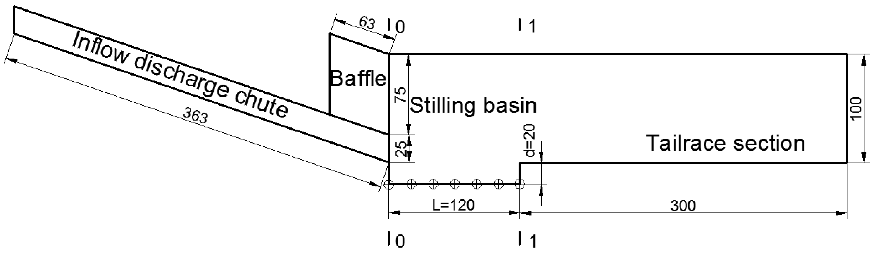
Experiments were conducted in a smoothened glass flume. It was composed of several sections including a 363 cm-length inflow discharge chute, baffle, 120 cm-length stilling basin with shallow-water cushion, and 300 cm-length tail water section (Longitudinal cross-sectional view as shown in Figure 1). The discharge chute section and all downstream parts were with rectangular cross section, with a width of 30 cm. The inlet control is a gate that is 10 cm wide, which controls the head of water to the inflow discharge chute. The slope of the inflow discharge chute used in this study is fixed to 17°. At downstream, the water level was controlled, and outflow condition was applied.
2.2. Mathematical Model
In the present study, ANSYS 16.0 was utilized to investigate the flow characteristics over the stilling basin with shallow-water cushion with different Froude numbers. An iterative format selected an implicit time-marching scheme. The volume of fluid (VOF) [16,17] method was adopted to track and simulate the free surface and two-phase flow of air and water. The mathematical model of 3D large eddy simulation (LES) was used in the calculation, which is introduced below.
(1) Governing equations
In LES [18,19,20,21,22], the large-scale eddy was simulated directly by solving the momentum equation, and the small-scale eddy was expressed in the sub-grid scale model. The governing equation was,
where, the value with “–” represents the large-scale value obtained after filtering; ρ represents the density; U represents the velocity; t represents the time; p represents the pressure; g represents the acceleration of gravity; x represents the coordinate; i, j represents the coordinate orientation; and represents the sub-grid stress, which indicates the impact caused by small-eddy movement on the large-eddy movement. Generally, the sub-grid stress is calculated by the eddy viscidity model,
where, represents the sub-grid turbulent viscosity coefficient, ; represents the strain rate tensor under the scale to be solved, which is defined as;
The Smagorinsky–Lilly model is used to calculate the sub-grid turbulent viscosity coefficient: , ; where, represents the mixed length of the sub-grid scale; represents the Karman constant; d represents the distance to the nearest wall face; V represents the volume of computing control body; and represents the Smagorinsky constant, which is 0.1 in this study [23].
(2) Discretization and algorithm
In this test, the finite volume method [24] was used to discrete of the governing equations, and second-order implicit scheme was used in the discretization of time item, and the PISO algorithm [25,26,27] was used to solve and control the coupling of speed and pressure in the equation. The VOF [16,17] method was adopted to track and simulate the free surface and two-phase flow of air and water.
(3) Computational domain and boundary conditions
(1) Computational domain
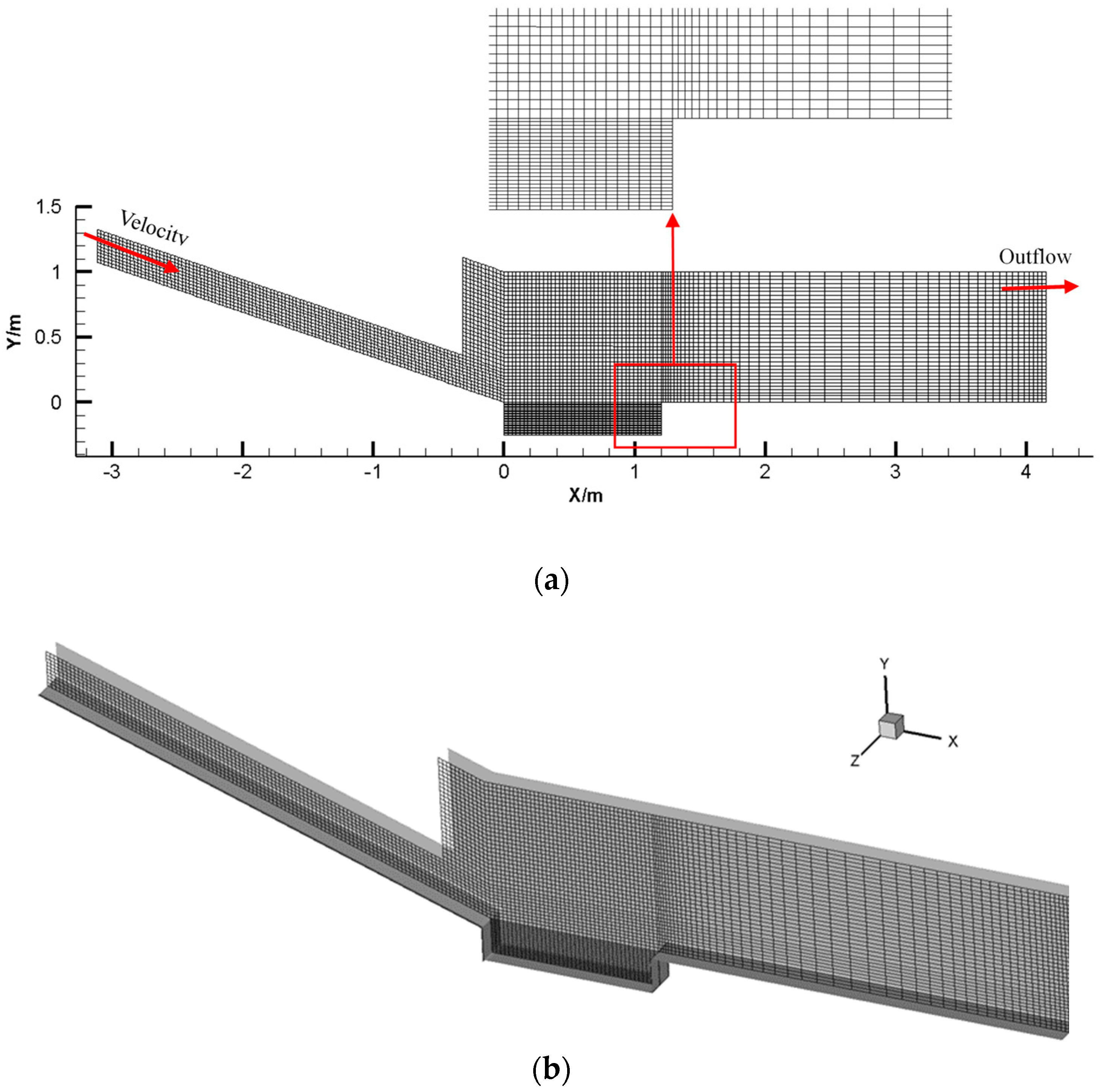
The computational domain and grid are shown in Figure 2 with the same dimensions as Figure 1. The longitudinal cross-section in Figure 2a is located at the center of Figure 2b. The grids in the stilling basin and tail water section were transited from coarse to fine from top to bottom, of which size is 2–3 cm, and the total grids of the model is 272,000.
(2) Boundary conditions
The boundary condition of the inlet of the chute was set as velocity inlet condition which could be determined according to the flow and the area of inlet of the chute. The outflow condition [28] was applied at the outlet boundary. The viscous sub-layer of the near wall was treated by the wall function method [29]. Non-slip condition was applied on the fixed wall.
2.3. Verification of Mathematical Model
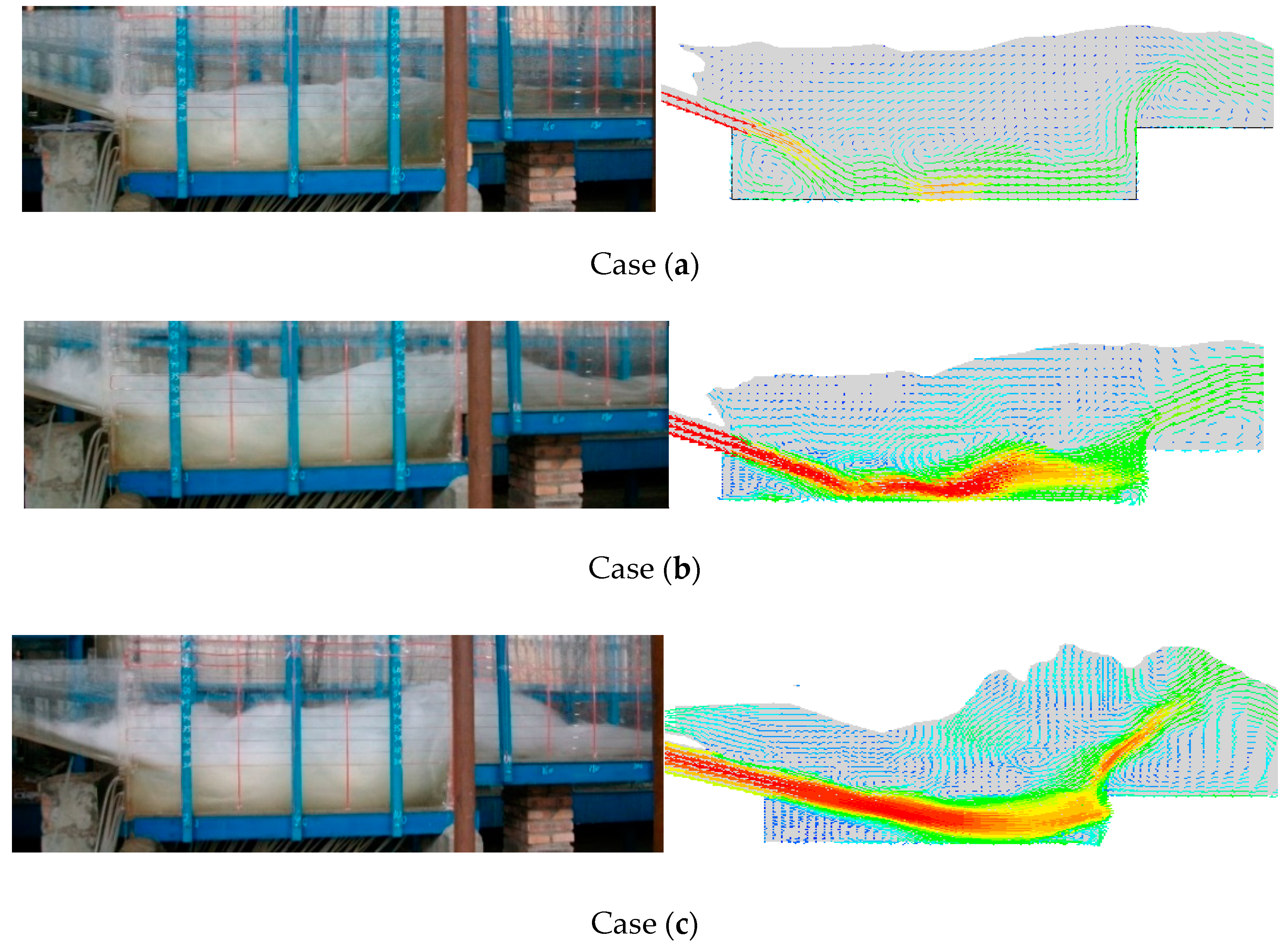
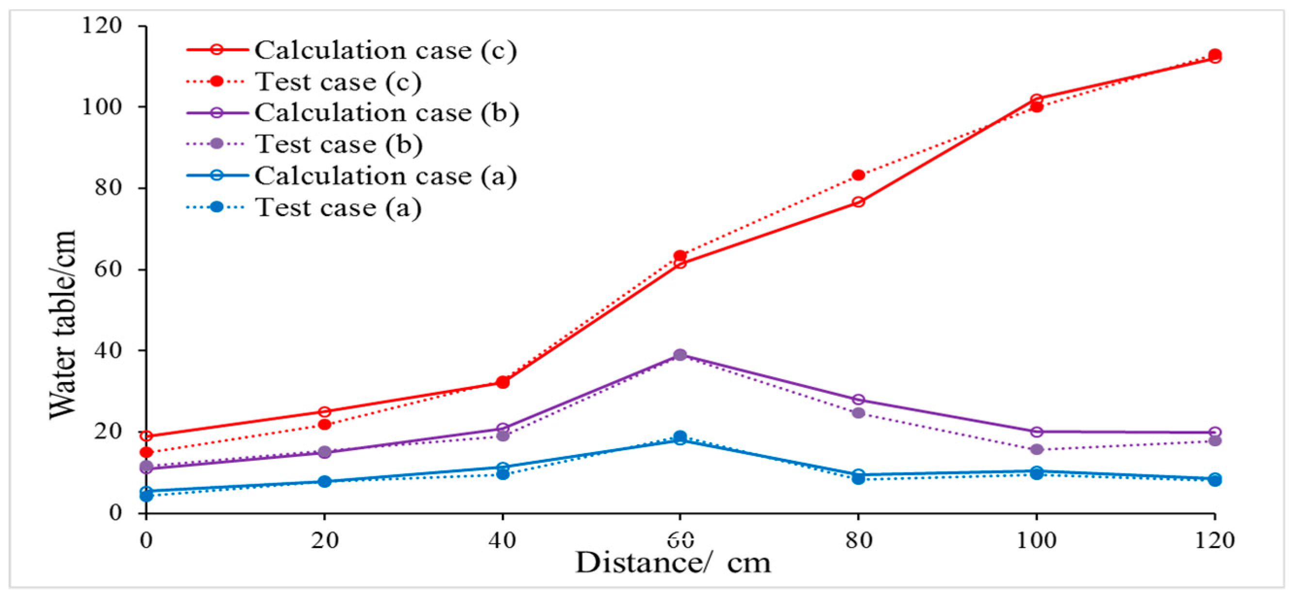
The calculation results of the large eddy simulation were compared with the test results of three cases based on the Froude number (Fr) at the inlet of stilling basin and the depth of SBSWC, which are (a) Fr = 6.92, d = 20 cm, (b) Fr =7.64, d = 15 cm, and (c) Fr = 9.25, d = 25 cm, respectively.
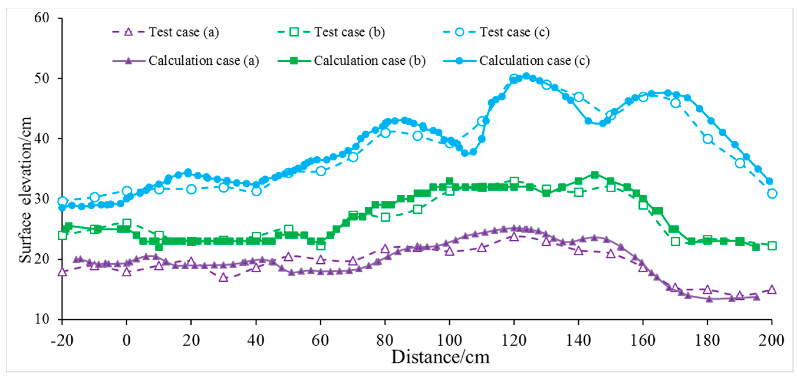
The reliability and accuracy of LES for this study were verified by the computing and experimental results. Similar hydraulic jumps in the stilling basin were observed from the regime of both the test and computation (Figure 3) in all 3 cases, and the numerical model captured the flow profiles [30] accurately compared with test data (Figure 4) and the differences of the average pressure between test results and calculated results (Figure 5) were very small except for individual locations in case 3.
It can be seen from Figure 4 and Figure 5 that, at most locations, the calculated results were fairly consistent with that of laboratory tests. The maximums of the relative error for flow profile and average pressure were 7.1% and 6.5%, respectively, indicating that the numerical simulations produced reliable and acceptable results.
3. Results and Discussion
A systematic study by means of LES was conducted to simulate the hydraulic characteristics such as flow regime, main stream location, and unit volume energy dissipation rate to determine the best depth of the shallow-water cushion on 30 cases including five typical Froude numbers and six different depths of shallow-water cushion shown in Table 1.
3.1. Flow Regime
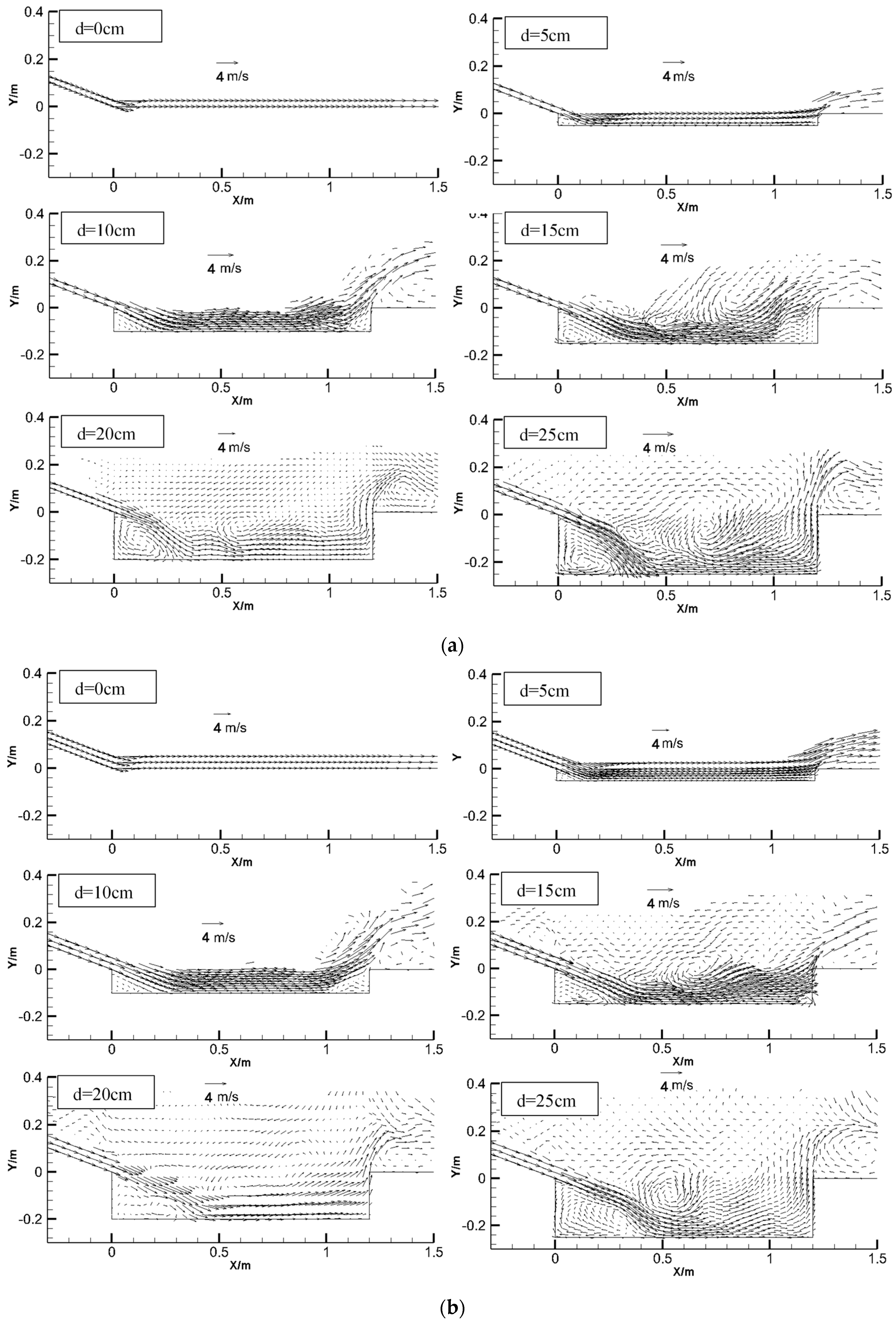
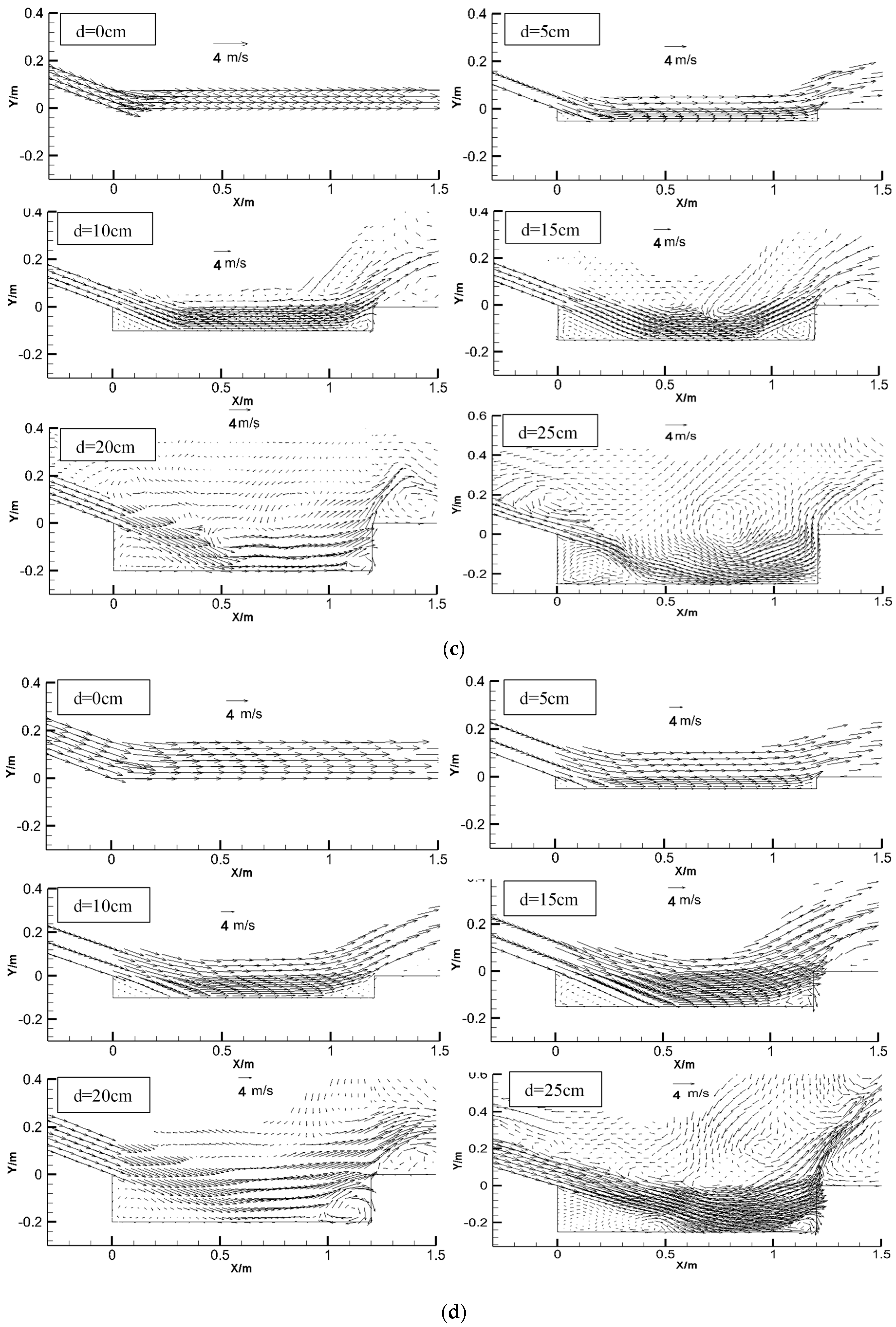
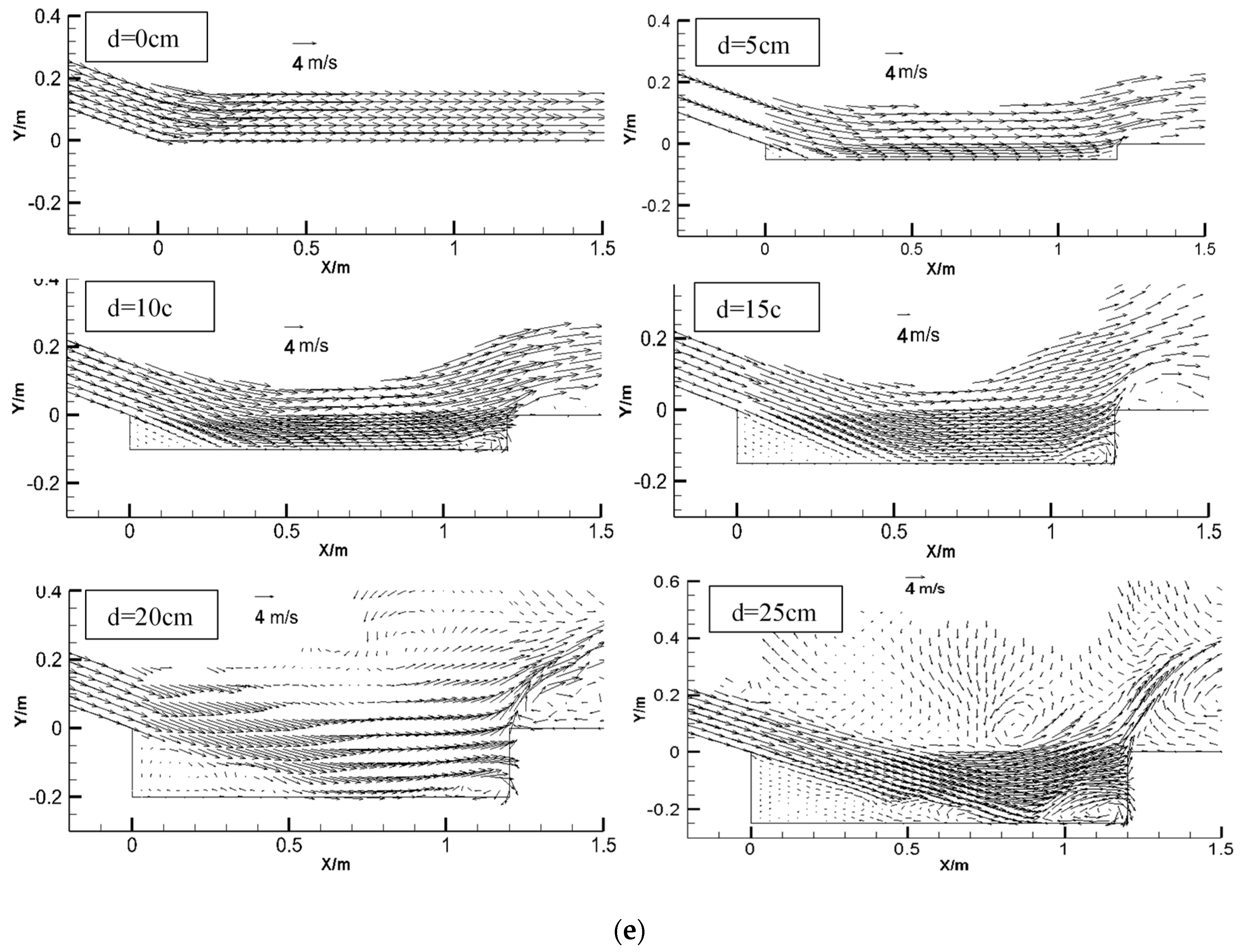
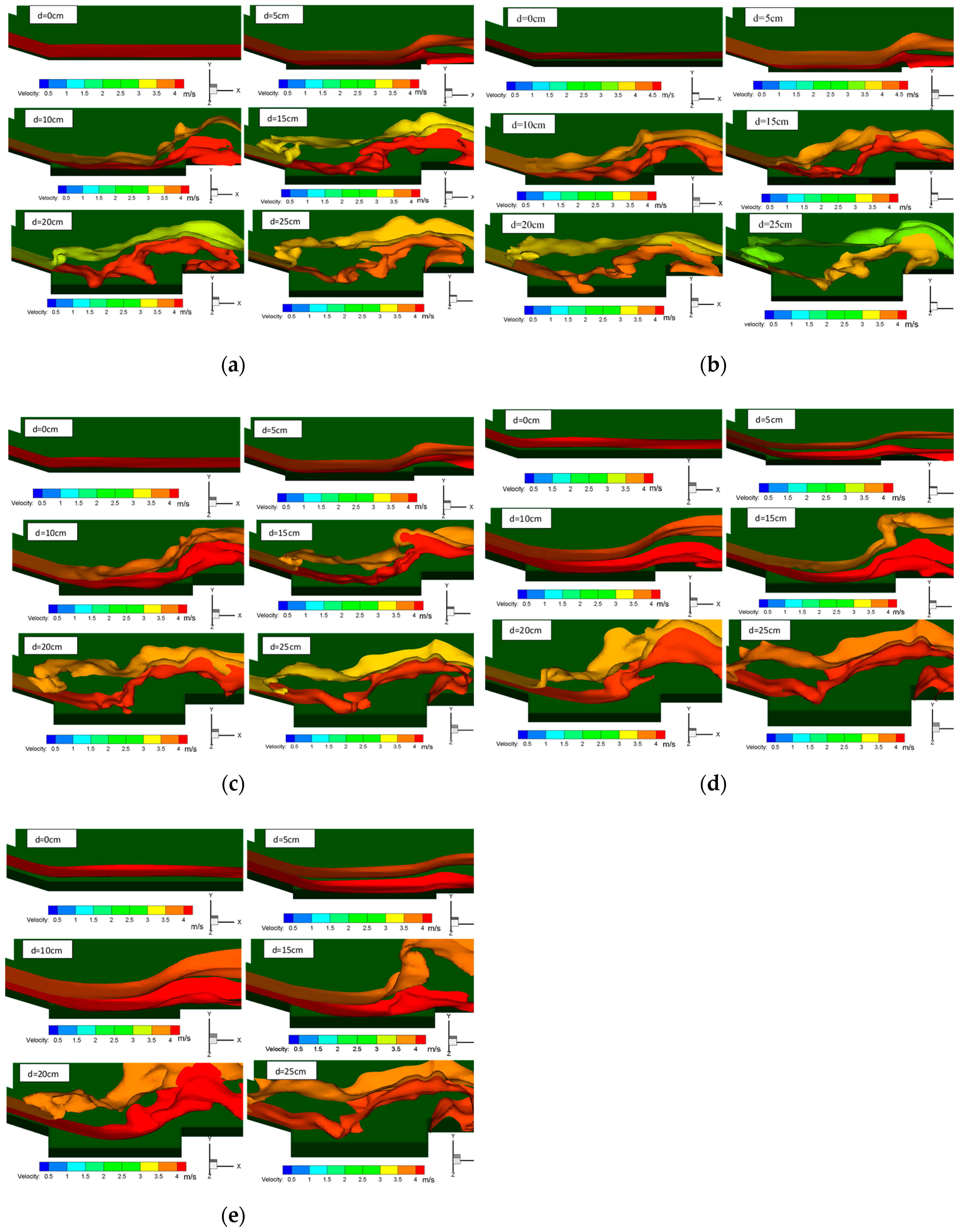
The regimes of hydraulic jumps in the stilling basin at different conditions were presented in Figure 6. Since it was not possible to calculate every depth as a calculated working condition, the same six depths were selected for each Froude number, which were 0, 5, 10, 15, 20, and 25 cm respectively. Therefore, the calculated best depth in each corresponding Froude has an error of ±2.5 cm.
It is seen that the regimes and velocity distribution are different in the stilling basins for different depths with the same Froude number and with different Froude number but same depth. For the same Froude number, if the depth is not enough, no hydraulic jump takes place in the basin, and the regime of jump gets more complete as the depth increases; for example, when the depth of stilling basin is 0 cm or 5 cm, there is no hydraulic jump in the stilling basin; when the depth of stilling basin is 10 cm, 15 cm, 20 cm, or 25 cm, there is a hydraulic jump in the stilling basin. This pattern holds for all the groups (a)–(e) with different Froude numbers. For different Froude numbers, the depth required to form a complete hydraulic jump is different. For example, a complete hydraulic jump occurred in the depth of 15 cm, 20 cm, and 25 cm in the stilling basin when the Froude numbers are 7.64 and 6.92. In case that the Froude number is 8.05 and 9.25, the complete hydraulic jump occurred in the depth of 20 and 25 cm in the stilling basin. While in the case of Froude number 11.24, the complete hydraulic jump occurs in the depth of 25 cm in the stilling basin.
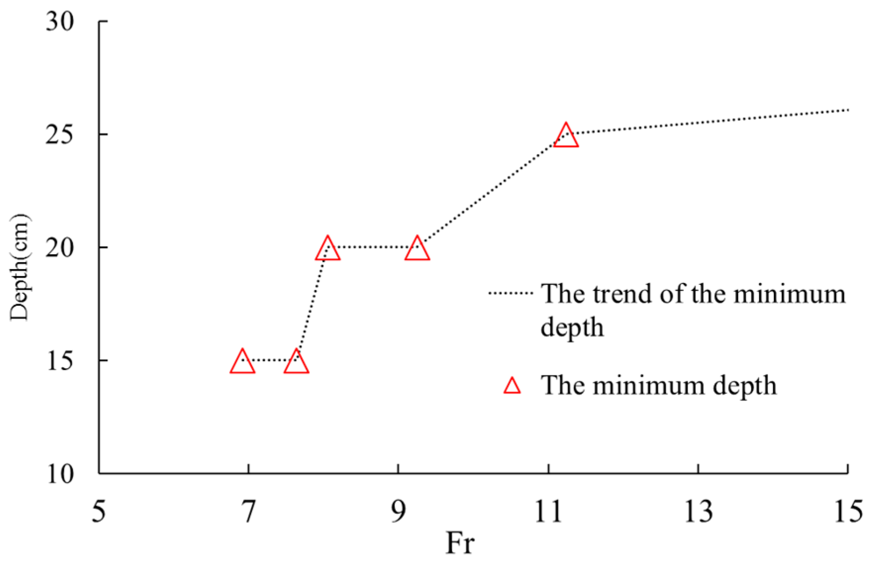
From the prospective of flow regime, the minimum depth of stilling basin with shallow water cushion (SBSWC) with different Froude numbers were depicted in Figure 7. It is indicated that the higher the Froude number, the deeper the basin required to form a complete hydraulic jump. In detail, in cases that the Froude number are 6.92, 7.64, 8.05, 9.25, and 11.24, the minimum depths of stilling basin with shallow water cushion are 15 cm, 15 cm, 20 cm, 20 cm and 25 cm.
3.2. Main Stream Location
The main stream zone was defined as the area that the flow speed was larger than the average speed of cross section in this study. The water cushion was then defined as the water body under the lower boundary of the main stream and the dimensionless thickness of water cushion was defined as the thickness of water cushion referred to the depth of the basin.
The main stream location of the 30 cases were grouped and shown in Figure 8 in which the main stream was represented out by velocity iso-surface in some cases. It shows that the center of the main stream closest to the bottom of the basin is located at about 1/3 depth of the basin from the bottom in cases that hydraulic jumps occur which agrees with the results of previous study [7]. In cases that the Froude numbers are 6.92, 7.64, and 8.05, it can be clearly observed that the water cushions are formed between the main stream and the cushion bottom in the cases of the stilling basin depth of 15 cm, 20 cm and 25 cm. While in the case of Froude number 9.25 and 11.24 the water cushion locates between the main stream and the cushion bottom when the stilling basin depth is 20 cm or 25 cm.
Among the 30 cases, for each Froude number, the minimum dimensionless thickness (T) of water cushion (depth of water cushion over depth of stilling basin) varies with the depth of the stilling basin (Table 2). It is seen that the thickness are different in the stilling basins with different depths with the same Froude number and with different Froude number but same depth. For the same Froude number, the deeper the stilling basin, the thicker the thickness of the water cushion. For the same depth, the bigger the Froude number, the thinner the thickness of the water cushion.
3.3. Energy Dissipation Rate
The energy dissipation [31] rate of the stilling basin could be expressed as Equation (5),
In which, E0 and E1 stand for the energy of the control section at the inlet and outlet of the stilling basin and taken the elevation at the tailrace section as the reference elevation in Figure 1.
Then the unit volume energy dissipation rate could be defined by Equation (6),
where, is the unit volume (dimensionless) energy dissipation rate; is dimensionless volume; is the volume of the stilling basin, L, d and B are the length, the depth and the width of the stilling basin respectively, is the volume of the water between inlet and outlet of the stilling basin.
The energy dissipation rates of the 30 cases were calculated and listed in Table 3, in which, column 1 is the Froude number at inlet of the stilling basin; column 2 is the depth of the stilling basin; column 3 is the ratio of the depth to length of the stilling basin (the total length is 120 cm); columns 4 to 10 are the mean speed of different cross sections (the heads of 0, 20, 40, 60, 80, 100, and 120 indicate the distance of the cross sections away from the inlet of the stilling basin entrance with the unit of cm); column 11 is the energy dissipation rate; column 12 is the dimensionless volume of the stilling basin; and column 13 is the unit volume energy dissipation rate.
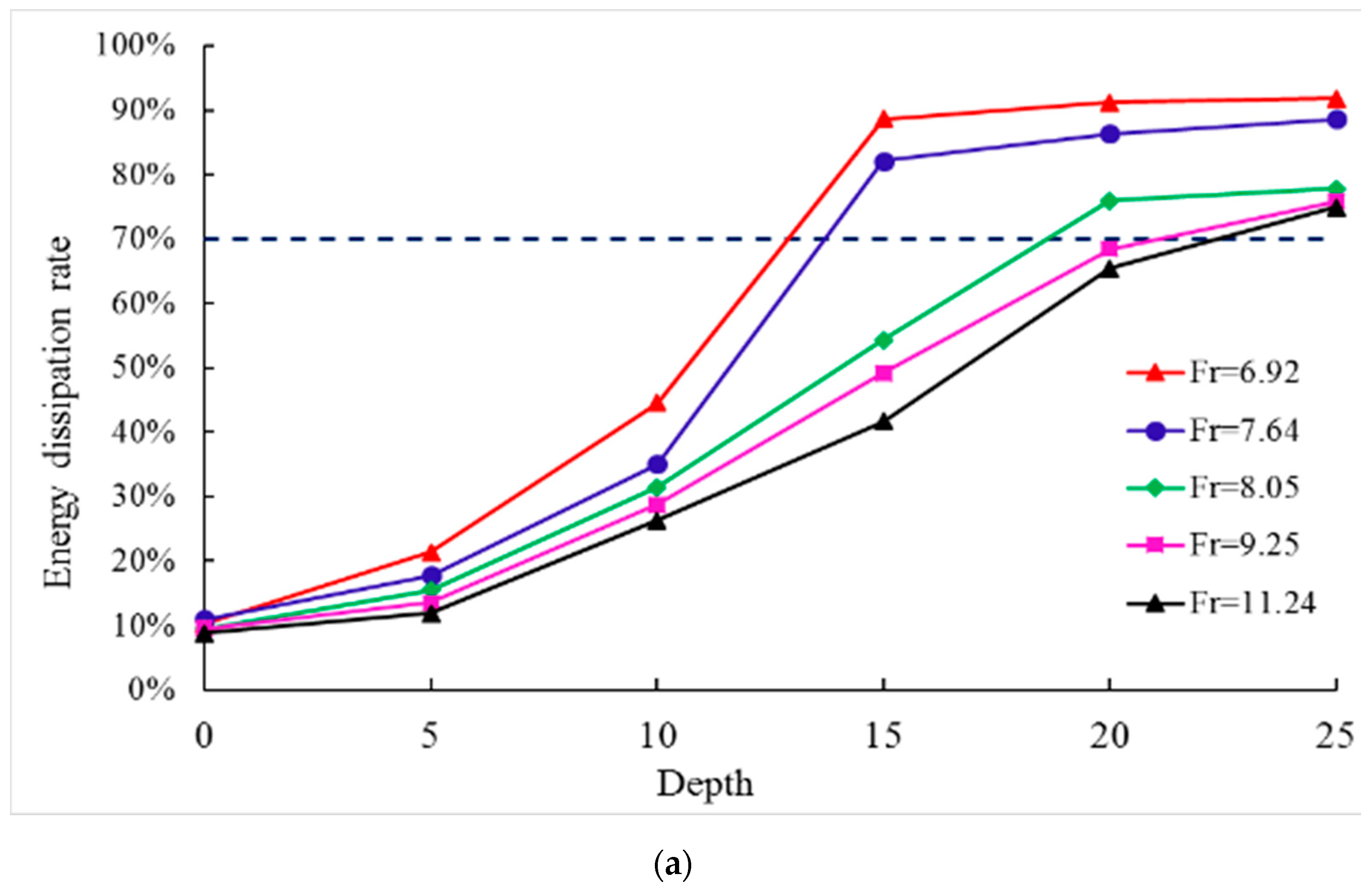
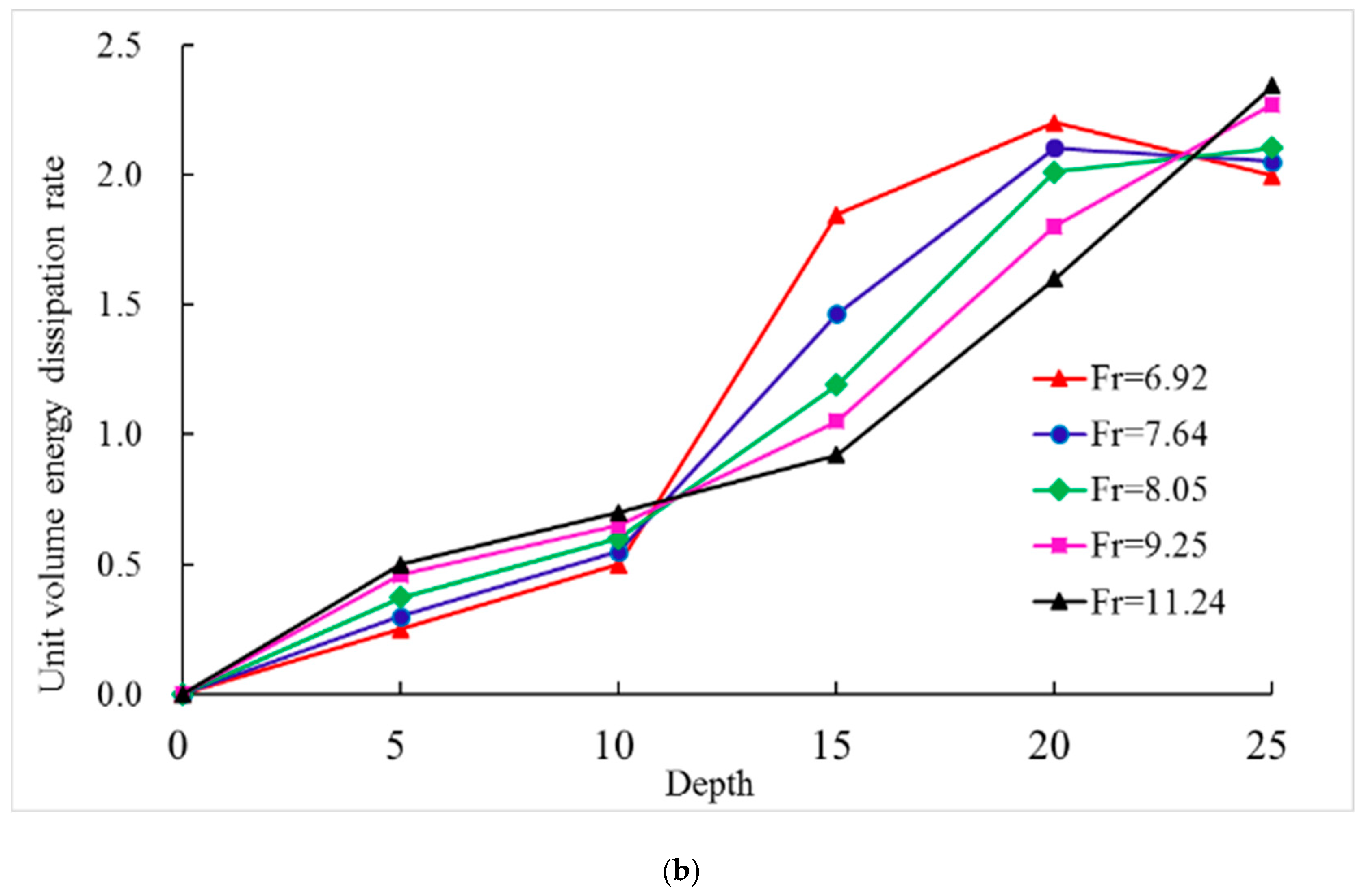
Using columns 2, 11, and 13 in Table 3, the energy dissipation rate and the unit volume energy dissipation rate related with the depth of the stilling basin were calculated and depicted in Figure 9 with the different Froude number as a parameter.
Generally speaking, the total energy dissipation (e) increases rapidly with the depth of the basin and changes little after reaching a certain value with the depth (Figure 9a); whereas, when the Froude number is smaller, the unit volume energy dissipation rate goes high with the increase of the depth first, and then drops down after reaching the maximum value, which means some of the water body does not involve the energy dissipation (Figure 9b); when the Froude number is larger, it goes higher with the increase of the depth. It also shows that the total energy dissipation reaches the maximum but the unit volume energy dissipation rate may not reach its maximum value, which indicates the depth of the basin is not good enough for the hydraulic jump; for example, the unit volume energy dissipation rate keep increasing with Froude number in the cases of Froude numbers equal to 9.25 and 11.24 which means the depth of 25 cm is sufficient for them getting to the maximum unit volume energy dissipation rates in the study.
3.4. The Best Depth of the Stilling Basin
For a given Froude number, it is expected that a complete hydraulic jump occurs in the stilling basin and the velocity near the bottom is relatively low and with a high energy dissipation rate in total and per volume. From the perspectives of flow regime, total energy dissipation rate and bottom velocity, the deeper a stilling basin is, more easily a complete hydraulic jump forms, higher the total energy dissipation rate and farther the main stream away from the bottom of the basin; however, from the perspective of the unit volume energy dissipation rate, the depth of the basin should not be too large, it otherwise is a waste as part of the water body in the basin is not involved in the energy dissipation. In addition, the thickness of the water cushion may be too large to regard the stilling basin as a ‘shallow-water cushion’ stilling basin and may be turned into a plunge pool which performs very different than the stilling basin with shallow water cushion in energy dissipation. Therefore, according to the results above of flow regime, flow profile, main stream location, energy dissipation, etc., the standards for defining the best depth of the stilling basin with shallow-water cushion can be proposed as (1) a complete hydraulic jump must occur in the basin (2) the thickness of water cushion is about 1/10–1/3 deep of the basin, and (3) the energy dissipation rate is more than 70% and the unit volume energy dissipation rate is as high as possible.
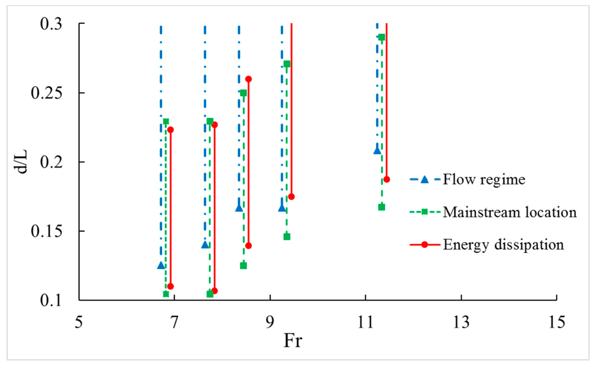
According to the definition for the best depth of SBSWC, three ranges of the depth were depicted in the 5 different Froude numbers respectively.in Figure 10. The blue line stands for the depth range for the standard (1) of flow regime according to the minimum depth for a complete hydraulic jump from Figure 6, and the green line stands for the depth range for the standard (2) of the relationship between the main stream and the thickness of the water cushion in Figure 8 and Table 2, and the red line stands for the depth range for the standard (3) of energy dissipation according to Table 3 and Figure 9. It is shown that all the 3 standards are necessary to obtain the range as neither the minimums nor the maximums of the range can be determined by the same standard alone for different Froude numbers. For example, for cases of Froude numbers equal to 6.92 and 9.25, the minimums are determined by the standards of flow regime and energy dissipation, respectively, while the maximums by energy dissipation and main stream location, respectively.
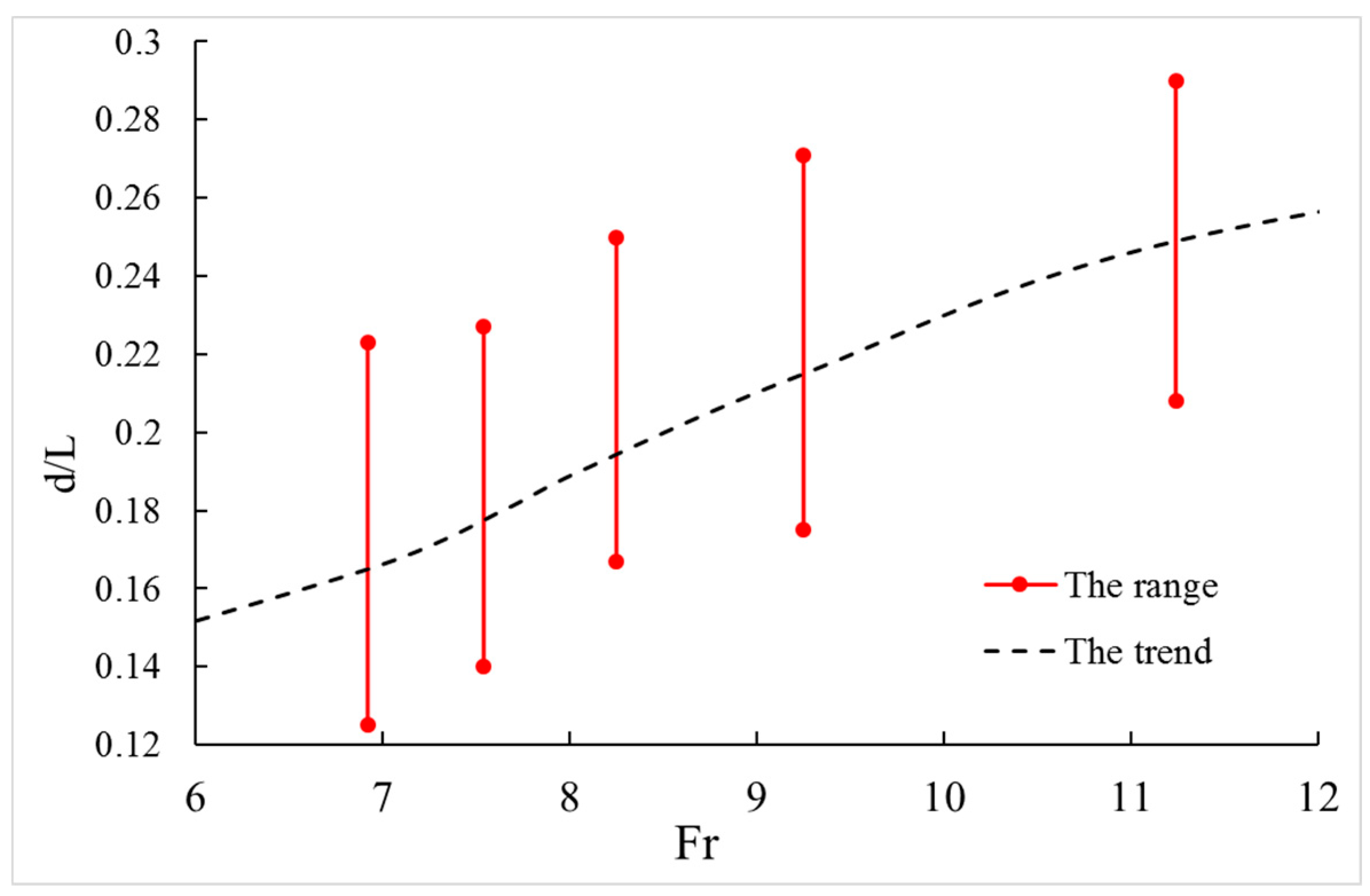
The overlap of all the three ranges for the same Froude number represented that the three standards were met in this integral (the integral between the maximum of the 3 minimums and the minimum of the maximums) and its mean is taken as the best depth of the stilling basin with shallow-water cushion shown in Figure 11 where the dimensionless depth (d/L, the depth over the length of the stilling basin) was adopted. It indicates that the ranges of the best depth are large for some cases while small for some other cases and that the best depth of the stilling basin increases with the increase of the Froude number.
4. Conclusions
In this study, 30 cases consisting of five different Froude numbers and six depths were selected for which large eddy simulation (LES) was adopted to simulate the hydraulic characteristics in the stilling basin, including the flow regime of hydraulic jump, the location of the main stream and the unit volume energy dissipation rate. The following conclusions can be drawn:
- After comparing large eddy simulation calculation results and model tests, the computation of the flow profile and hydraulic jumps were similar to the test, and the differences of the average pressure between test results and calculated results were very small except for individual locations. The numerical data and experimental results were in good agreement, indicating the reliability and accuracy of LES in the present work.
- Based on the experimental results of flow regime of hydraulic jump, the location of the main stream and the energy dissipation rate, for the first time three standards of the best depth of stilling basin with shallow water cushion (SBSWC) are proposed in this paper; namely, (1) a complete hydraulic jump must occur in the basin (2) the thickness of water cushion is about 1/10–1/3 deep of the basin, and (3) the energy dissipation rate is more than 70% and the unit volume energy dissipation rate is as high as possible.
- According to the definition for the best depth of SBSWC, three ranges of the depth were depicted in the 5 different Froude numbers respectively. Therefore, the overlapping sections are the range of the best depth of stilling basin with shallow water cushion for this study.
- It showed that the best depth radio of stilling basin with shallow-water cushion (depth to length ratio) was between 0.1 and 0.3 and it also indicated that the best depth of the stilling basin with shallow water cushion increased with the increase of Froude number. The results in this paper are of significance for design and optimizing of SBSWC.
Author Contributions
Q.L. carried out the model simulations and result analysis as well as writing of the manuscript. L.L. provided the prototype field data and relevant engineering documents. H.L. took the leadership of whole project and participated in the discussion and decision-making process. All the authors participated and contributed to the final manuscript.
Funding
This research work was supported by the National Key Research Development Plan (No. 2016YFC0401705), National Natural Science Foundation of China (No. 51209154), (No. 51079091), and Sichuan Youth Innovation Team Project (No. 2016TD0020).
Conflicts of Interest
The authors declare no conflict of interest.
References
- Chanson, H. Current knowledge in hydraulic jumps and related phenomena. A survey of experimental results. Eur. J. Mech. B Fluids 2009, 28, 191–210. [Google Scholar] [CrossRef] [Green Version]
- Alikhani, A.; Behrozi-Rad, R.; Fathi-Moghadam, M. Hydraulic jump in stilling basin with vertical end sill. Int. J. Phys. Sci. 2010, 5, 25–29. Retrieved from http://www.academicjournals.org/IJPS.
- Chanson, H. Hydraulic condition for undular-jump formations. J. Hydraul. Res. 2001, 39, 203–209. [Google Scholar] [CrossRef]
- Zare, H.K.; Doering, J.C. Forced Hydraulic Jumps below Abrupt Expansions. J. Hydraul. Eng. 2011, 137, 825–835. [Google Scholar] [CrossRef]
- Champagne, T.M.; Barlock, R.R.; Ghimire, S.R.; Barkdoll, B.D.; Gonzalez-Castro, J.A.; Deaton, L. Scour Reduction by Air Injection Downstream of Stilling Basins: Optimal Configuration Determination by Experimentation. J. Irrig. Drain. Eng. 2016, 142. [Google Scholar] [CrossRef]
- Tianxiang, L.I. Investigation on Hydraulic Performances of Stilling Basin with Shallow-Water Cushion. Master’s Thesis, State Key Laboratory of Hydraulics and Mountain River R & D in Sichuan University, Chengdu, China, 2006. [Google Scholar]
- Li, L.X.; Liao, H.S.; Liu, D.; Jiang, S.Y. Experimental investigation of the optimization of stilling basin with shallow water cushion used for low Froude number energy dissipation. J. Hydrodyn. B Ser. 2015, 27, 522–529. [Google Scholar] [CrossRef]
- Liu, D.; Li, L.X.; Huang, B.S.; Liao, H.S. Numerical Simulation and Experimental Investigation on Stilling Basin with Double Shallow-water Cushions. J. Hydraul. Eng. 2012, 623–630. [Google Scholar] [CrossRef]
- Hager, W.H.; Kawagoshi, N. Hydraulic jumps at rounded drop. Proc. Inst. Civ. Eng. Part Res. Theory 1990, 89, 443–470. [Google Scholar] [CrossRef]
- Eroǧlu, N.; Tokyay, N. Statistical approach to geometric properties of wave-type flow occurring at an abrupt drop. J. Fac. Eng. Archit. Gazi Univ. 2012, 27, 911–919. [Google Scholar]
- Rice, C.E.; Kadavy, K.C. Riprap design upstream of straight drop spillways. Trans. Asae 1992, 34, 1715–1725. [Google Scholar] [CrossRef]
- Ram, K.V.; Prasad, S.; Spatial, R. B-Jump at Sudden Channel Enlargements with Abrupt Drop. J. Hydraul. Eng. 1998, 124, 643–646. [Google Scholar] [CrossRef]
- Sabzkoohi, A.M.; Kashefipour, S.M.; Bina, M. Investigation of effective parameters on stepped and straight drops energy dissipation using physical modeling. J. Food Agric. Environ. 2011, 9, 748–753. Retrieved from https://www.researchgate.net/publication/286803391.
- Riazi, R.; Bejestan, M.S.; Kashkouli, H.; Khosrojerdi, A. Effect of roughness on characteristics of bed B-jump in stilling basin with abrupt drop. Res. Crops 2012, 13, 1137–1141. Retrieved from https://www.researchgate.net/publication/287059975.
- Ilie, M. Fluid-structure interaction in turbulent flows; a CFD based aeroelastic algorithm using LES. Appl. Math. Comput. 2018, 342, 309–321. [Google Scholar] [CrossRef]
- Wanik, A.; Schnell, U. Some remarks on the PISO and SIMPLE algorithms for steady turbulent flow problems. Comput. Fluids 1989, 17, 555–570. [Google Scholar] [CrossRef]
- Wang, T.; Gu, C.G.; Yang, B. PISO algorithm for unsteady flow field. J. Hydrodyn. 2003. [Google Scholar] [CrossRef]
- Moeng, C.H. A Large-Eddy-Simulation Model for the Study of Planetary Boundary-Layer Turbulence. J. Atmos. Sci. 1984, 41, 2052–2062. [Google Scholar] [CrossRef] [Green Version]
- Moin, P.; Kim, J. Numerical investigation of turbulent channel flow. J. Fluid Mech. 2006, 118, 1280–1284. [Google Scholar] [CrossRef]
- Sarfaraz, M. Numerical Computation of Inception Point Location for Steeply Sloping Stepped Spillways. In Proceedings of the 9th International Congress on Civil Engineering, Isfahan University of Technology (IUT), Isfahan, Iran, 18–20 December 2012. [Google Scholar]
- Smagorinsky, J.S.; Smagorinsky, J. General Circulation Experiments with the Primitive Equations. Mon. Weather Rev. 1963, 91, 99–164. [Google Scholar] [CrossRef]
- Song, C.C.S. A weakly compressible flow model and rapid convergence methods. J. Fluids Eng. 1988, 110, 441–445. [Google Scholar] [CrossRef]
- Canuto, V.M.; Cheng, Y. Determination of the Smagorinsky–Lilly constant CS. Phys. Fluids 1997, 9, 1368–1378. [Google Scholar] [CrossRef]
- Issa, R.I. Solution of the Implicitly Discretised Fluid Flow Equations by Operator-Splitting. J. Comput. Phys. 1986, 62, 40–65. [Google Scholar] [CrossRef]
- Hirt, C.W.; Nichols, B.D.; Romero, N.C. SOLA: A Numerical Solution Algorithm for Transient Fluid Flows (LA-5852); Los Alamos Scientific Laboratory: Los Alamos, NM, USA, 1988. [CrossRef]
- Nichols, B.D.; Hirt, C.W.; Hotchkiss, R.S. SOLA-VOF: A Solution Algorithm for Transient Fluid Flow with Multiple Free Boundaries (LA-8355); Nasa Sti/recon Technical Report N.; Los Alamos Scientific Laboratory: Los Alamos, NM, USA, 1980.
- Nichols, B.D.; Hirt, C.W.; Hotchkiss, R.S. A fractional volume of fluid method for free boundary dynamics. In Seventh International Conference on Numerical Methods in Fluid Dynamics; Springer: Berlin/Heidelberg, Germany, 1981. [Google Scholar]
- Mossa, M.; Petrillo, A.; Chanson, H. Tail-water level effects on flow conditions at an abrupt drop. J. Hydraul. Res. 2003, 41, 39–51. [Google Scholar] [CrossRef]
- Felder, S.; Chanson, H. Air-water flow patterns of hydraulic jumps on uniform beds macroroughness. J. Hydraul. Eng. 2017, 144. [Google Scholar] [CrossRef]
- Pagliara, S.; Palermo, M. Hydraulic jumps on rough and smooth beds: Aggregate approach for horizontal and adverse-sloped beds. J. Hydraul. Res. 2015, 53, 243–252. [Google Scholar] [CrossRef]
- Palermo, M.; Pagliara, S. Semi-theoretical approach for energy dissipation estimation at hydraulic jumps in rough sloped channels. J. Hydraul. Res. 2018. [Google Scholar] [CrossRef]
Figure 1.
Schematic design of the model test (in cm).

Figure 2.
Schematic diagram for computational domain and grids of mathematical model. (a) Axial cross-sectional view; (b) The entire calculation domain.
Figure 2.
Schematic diagram for computational domain and grids of mathematical model. (a) Axial cross-sectional view; (b) The entire calculation domain.

Figure 3.
Schematic diagram for flow regimes under three cases.

Figure 4.
Comparison of flow profile.

Figure 5.
Comparison of average pressure.

Figure 6.
Flow regimes and velocity distribution at axial plane. (a) Fr = 6.92; (b) Fr = 7.64; (c) Fr = 8.05; (d) Fr = 9.25; (e) Fr = 11.24. Fr: Froude number.
Figure 6.
Flow regimes and velocity distribution at axial plane. (a) Fr = 6.92; (b) Fr = 7.64; (c) Fr = 8.05; (d) Fr = 9.25; (e) Fr = 11.24. Fr: Froude number.


Figure 7.
The minimum depth of the stilling basin for the complete hydraulic jump.

Figure 8.
Main stream position in stilling basin. (a) Fr = 6.92; (b) Fr = 7.64; (c) Fr = 8.05; (d) Fr = 9.25; (e) Fr = 11.24.
Figure 8.
Main stream position in stilling basin. (a) Fr = 6.92; (b) Fr = 7.64; (c) Fr = 8.05; (d) Fr = 9.25; (e) Fr = 11.24.

Figure 9.
Energy dissipation rate. (a) Energy dissipation rate; (b) Unit volume energy dissipation rate.
Figure 9.
Energy dissipation rate. (a) Energy dissipation rate; (b) Unit volume energy dissipation rate.


Figure 10.
The range of the best depth of the stilling basin under three judgment conditions.

Figure 11.
The range of the best depth of the stilling basin.


Table 1.
The case of Froude number corresponding to the depth of the stilling basin.
| Fr | d (cm) | d/L | Fr | d (cm) | d/L | Fr | d (cm) | d/L | Fr | d (cm) | d/L | Fr | d (cm) | d/L |
|---|---|---|---|---|---|---|---|---|---|---|---|---|---|---|
| 7.64 | 0 | 0.000 | 6.92 | 0 | 0.000 | 8.05 | 0 | 0.000 | 9.25 | 0 | 0.000 | 11.24 | 0 | 0.000 |
| 5 | 0.042 | 5 | 0.042 | 5 | 0.042 | 5 | 0.042 | 5 | 0.042 | |||||
| 10 | 0.083 | 10 | 0.083 | 10 | 0.083 | 10 | 0.083 | 10 | 0.083 | |||||
| 15 | 0.125 | 15 | 0.125 | 15 | 0.125 | 15 | 0.125 | 15 | 0.125 | |||||
| 20 | 0.167 | 20 | 0.167 | 20 | 0.167 | 20 | 0.167 | 20 | 0.167 | |||||
| 25 | 0.208 | 25 | 0.208 | 25 | 0.208 | 25 | 0.208 | 25 | 0.208 |
Table 2.
Minimum of the dimensionless thickness of the water cushion.
| Group | Fr | d = 0 | d = 5 cm | d = 10 cm | d = 15 cm | d = 20 cm | d = 25 cm |
|---|---|---|---|---|---|---|---|
| 1 | 6.92 | 0 | 0.08 | 0.09 | 0.13 | 0.15 | 0.16 |
| 2 | 7.64 | 0 | 0.08 | 0.08 | 0.13 | 0.14 | 0.14 |
| 3 | 8.05 | 0 | 0.07 | 0.09 | 0.12 | 0.13 | 0.13 |
| 4 | 9.25 | 0 | 0.06 | 0.07 | 0.09 | 0.11 | 0.12 |
| 5 | 11.24 | 0 | 0.06 | 0.04 | 0.08 | 0.10 | 0.11 |
Table 3.
The unit volume energy dissipation rate of the stilling basin.
| Fr (1) | d (cm) (2) | d/L (3) | V (m/s) at Different Sections | e (11) | (12) | (13) | ||||||
|---|---|---|---|---|---|---|---|---|---|---|---|---|
| 0 (4) | 20 (5) | 40 (6) | 60 (7) | 80 (8) | 100 (9) | 120 (10) | ||||||
| 7.64 | 0.00 | 0.00 | 4.25 | 4.25 | 4.28 | 4.18 | 4.13 | 4.10 | 4.01 | 10.98% | 0.00 | / |
| 5.00 | 0.04 | 4.19 | 3.87 | 4.30 | 4.20 | 4.20 | 4.05 | 3.80 | 17.75% | 0.76 | 0.30 | |
| 10.00 | 0.08 | 3.60 | 3.30 | 3.50 | 3.70 | 3.81 | 3.40 | 2.90 | 35.11% | 0.72 | 0.55 | |
| 15.00 | 0.13 | 2.84 | 3.15 | 2.30 | 1.48 | 1.36 | 1.25 | 1.20 | 82.15% | 0.56 | 1.46 | |
| 20.00 | 0.02 | 2.60 | 1.55 | 1.33 | 0.96 | 1.09 | 0.99 | 0.96 | 86.37% | 0.43 | 2.10 | |
| 25.00 | 0.21 | 1.66 | 1.75 | 1.23 | 0.76 | 0.77 | 0.68 | 0.56 | 88.62% | 0.45 | 2.05 | |
| 6.92 | 0.00 | 0.00 | 4.37 | 4.38 | 4.37 | 4.29 | 4.22 | 4.20 | 4.14 | 10.25% | 0.00 | / |
| 5.00 | 0.04 | 4.32 | 4.17 | 4.11 | 4.08 | 3.90 | 3.90 | 3.83 | 21.40% | 0.54 | 0.25 | |
| 10.00 | 0.08 | 4.07 | 3.89 | 3.85 | 3.88 | 3.80 | 3.50 | 3.03 | 44.58% | 0.62 | 0.50 | |
| 15.00 | 0.13 | 4.03 | 3.85 | 3.13 | 2.77 | 2.15 | 1.53 | 1.36 | 88.61% | 0.48 | 1.85 | |
| 20.00 | 0.02 | 3.30 | 1.73 | 1.55 | 1.13 | 0.91 | 0.73 | 0.98 | 91.18% | 0.44 | 2.20 | |
| 25.00 | 0.21 | 2.30 | 1.83 | 1.44 | 1.16 | 0.88 | 0.72 | 0.66 | 91.77% | 0.46 | 1.99 | |
| 8.05 | 0.00 | 0.00 | 7.78 | 7.63 | 7.54 | 7.43 | 7.51 | 7.46 | 7.40 | 9.53% | 0.00 | / |
| 5.00 | 0.04 | 7.90 | 7.55 | 7.49 | 7.43 | 7.35 | 7.30 | 7.26 | 15.55% | 0.42 | 0.37 | |
| 10.00 | 0.08 | 7.55 | 7.45 | 7.29 | 6.98 | 6.85 | 6.33 | 6.25 | 31.47% | 0.42 | 0.60 | |
| 15.00 | 0.13 | 7.53 | 7.20 | 6.70 | 6.50 | 6.29 | 5.94 | 5.09 | 54.31% | 0.46 | 1.19 | |
| 20.00 | 0.02 | 5.81 | 5.01 | 4.53 | 4.01 | 3.82 | 3.15 | 2.85 | 75.94% | 0.36 | 2.01 | |
| 25.00 | 0.21 | 4.73 | 4.16 | 3.86 | 3.38 | 3.19 | 2.65 | 2.23 | 77.77% | 0.37 | 2.10 | |
| 9.25 | 0.00 | 0.00 | 10.39 | 10.14 | 10.01 | 10.02 | 9.97 | 9.91 | 9.88 | 9.58% | 0.00 | / |
| 5.00 | 0.04 | 10.36 | 9.89 | 9.93 | 9.76 | 9.71 | 9.64 | 9.63 | 13.60% | 0.27 | 0.46 | |
| 10.00 | 0.08 | 10.20 | 9.77 | 9.53 | 9.52 | 9.44 | 9.29 | 8.61 | 28.75% | 0.45 | 0.65 | |
| 15.00 | 0.13 | 10.42 | 9.56 | 9.44 | 9.36 | 9.20 | 8.09 | 7.43 | 49.16% | 0.53 | 1.05 | |
| 20.00 | 0.02 | 9.44 | 9.49 | 9.26 | 8.79 | 7.85 | 6.25 | 5.30 | 68.48% | 0.43 | 1.80 | |
| 25.00 | 0.21 | 7.89 | 6.18 | 6.03 | 5.82 | 5.33 | 4.85 | 3.88 | 75.82% | 0.35 | 2.27 | |
| 11.24 | 0.00 | 0.00 | 13.36 | 13.11 | 13.12 | 13 | 12.92 | 12.88 | 12.76 | 8.78% | 0.00 | / |
| 5.00 | 0.04 | 13.23 | 12.96 | 12.88 | 12.69 | 12.43 | 12.42 | 12.42 | 11.87% | 0.26 | 0.50 | |
| 10.00 | 0.08 | 13.2 | 12.91 | 12.8 | 12.56 | 12.21 | 11.52 | 11.33 | 26.33% | 0.43 | 0.70 | |
| 15.00 | 0.13 | 13.19 | 12.88 | 12.62 | 12.12 | 11.63 | 11.15 | 10.07 | 41.71% | 0.31 | 0.92 | |
| 20.00 | 0.02 | 13.26 | 12.56 | 11.45 | 10.62 | 9.53 | 8.05 | 7.79 | 65.49% | 0.32 | 1.60 | |
| 25.00 | 0.21 | 12.21 | 11.64 | 10.88 | 9.48 | 8.38 | 7.23 | 6.11 | 74.96% | 0.32 | 2.34 | |
© 2018 by the authors. Licensee MDPI, Basel, Switzerland. This article is an open access article distributed under the terms and conditions of the Creative Commons Attribution (CC BY) license (http://creativecommons.org/licenses/by/4.0/).
Share and Cite
MDPI and ACS Style
Li, Q.; Li, L.; Liao, H. Study on the Best Depth of Stilling Basin with Shallow-Water Cushion. Water 2018, 10, 1801. https://doi.org/10.3390/w10121801
AMA Style
Li Q, Li L, Liao H. Study on the Best Depth of Stilling Basin with Shallow-Water Cushion. Water. 2018; 10(12):1801. https://doi.org/10.3390/w10121801
Chicago/Turabian StyleLi, Qiulin, Lianxia Li, and Huasheng Liao. 2018. "Study on the Best Depth of Stilling Basin with Shallow-Water Cushion" Water 10, no. 12: 1801. https://doi.org/10.3390/w10121801
Note that from the first issue of 2016, this journal uses article numbers instead of page numbers. See further details here.