System for Increasing the Seismic Safety of Pipelines in the Water Supply and Distribution Networks


1
Faculty of Civil Engineering and Building Services, Gheorghe Asachi Technical University of Iaşi, Dimitrie Mangeron Boulevard no. 1, 700050 Iași, Romania
2
Faculty of Civil Engineering, Technical University of Cluj-Napoca, 15 C-tin Daicoviciu Street, 400020 Cluj-Napoca, Romania
*
Author to whom correspondence should be addressed.
Water 2019, 11(5), 1049; https://doi.org/10.3390/w11051049
Submission received: 23 April 2019
/
Revised: 14 May 2019
/
Accepted: 17 May 2019
/
Published: 20 May 2019
(This article belongs to the Section Urban Water Management)
Abstract
:Seismic activity of small, medium or high intensity has a destructive effect on existing water supply and distribution networks. In the scholar literature, these are included in Class I—Vital Performance Systems, whose operation must be uninterrupted in case of a seismic event. Water networks are also essential for the safe operation of certain critical subsystems in the event of an earthquake (fire-extinguishing systems, etc.), in order to avoid loss of human lives, reduce adverse environmental impacts and limit damage caused by fires. The article proposes a seismic safety system for the water transport pipelines obtained by designing, executing and testing an experimental design, a system that can be used to increase the seismic resilience of the water supply and distribution network pipelines. The experimental data obtained were verified on the basis of the theoretical data available in the literature. The results of the research are particularly useful and can be proposed for use from the stage of designing new networks to providing expertise for existing networks, for establishing the most-stressed areas in which to be installed, and for implementing both execution and at the same time rehabilitation and upgrading.
1. Introduction
1.1. Background
The buried pipes for water distribution show a series of behavioural peculiarities both for static actions and for dynamic actions and especially for seismic action [1]. The behaviour of the pipelines is affected by various factors: The type of material the pipe is made from (its structure), its rigidity, the physical–mechanical characteristics of the earth mass in which it is embedded, the structure—ground massif interaction, the execution quality, etc. Among the dynamic actions to which the buried pipes must undergo stress are also those from the street traffic due to transport, the hydrodynamic pressure resulting from a sudden or very rapid change of the water flow regime, and among the most significant, seismic action [2]. The establishment of the category of behaviour of the circular section pipes is of particular importance for defining, as accurately as possible, the calculation models and then determining the state of strains and deformations as close as possible to the real state [3]. Even for low dynamic actions, such as those arising from heavy-duty transport or ram impact, solutions to protect the water pipeline are inefficient and for seismic actions they are totally lacking. Statistics and the scholarly literature contain little data on water supply and distribution-pipeline seismic engineering.
Practice has revealed that adductions and distribution networks are the most vulnerable to seismic action [4]. Their sensitivity to this type of action, even if of low intensity, is caused by the fact that they are carried out over extended areas, with large variability in the physical–mechanical features of the land in which they are located. The degree of vulnerability of water supply and distribution networks has led to the adoption of specific strategies for the protection of these structures against seismic activity (e.g., designing of expansion sleeves at the points of rigid pipe connections and the dimensioning of pipeline bridges to seismic stresses of a higher category with a unit of the seismic area of the site).
1.2. Current State of Research
A rational strategy, supported by the fact that in the immediate aftermath of an earthquake water demand increases, especially for fire extinction, is based on the concept of admitting minimal, controlled failures, which do not lead to the complete decommissioning of the water system [5].
Based on experience in the seismic actions of the water supply and distribution networks, the following statistical elements were broken down: In a large proportion, pipe failure occurs through transverse rupture, and ruptures in the stiffening areas (anchorage massifs, manholes, and building foundations) [6]. A conclusion can be drawn that most of the damage suffered by pipelines was where the route coincided with the direction of seismic wave propagation. Also, the laying of pipelines on land with large variations in physical and mechanical properties, without additional measures of anti-seismic protection, leads to a worsening of the behaviour of the entire network to seismic action. Plastic, steel and ductile cast iron pipes do best with dynamic stresses followed by reinforced concrete and pre-stressed concrete, cast iron, pure concrete, artificial basalt and ceramic material pipes.
Tubes and pipes for water pipelines in the water supply and distribution systems were made of the following materials: Asbestos (currently forbidden), reinforced concrete, plastics, grey cast iron, steel, etc. In the case of pipes below 400 mm in diameter, the most used material is cast iron and then plastics [7,8].
According to some studies, the outbreak of a post-seismic fire has the most devastating effects [4,8]. In the earthquake of 1906 in San Francisco, USA—known as the biggest urban disaster produced in peacetime—to the one that occurred in Asia in 2006, damage to water distribution pipelines has impeded interventions to extinguish the fire, with consequent human and material damage being major: 3000 dead persons and the destruction of 28,000 buildings. The Kobe earthquake of 1995 also caused serious damage to the water supply system, so the firefighters were forced to intervene in extinguishing fires by pumping water from the sea [8]. Water distribution networks are part of the life-line system and are defined as critical infrastructures for an urban settlement [9]. Their decommissioning, even for a short period of time as in the case of a seismic event, creates disaster-generating risks, with a major impact on civil protection and on the safety of major objectives.
1.3. Theoretical Considerations Regarding the Pipeline Behaviour to Seismic Actions
In specialty studies it is taken into consideration that in the case of the water distribution pipes, the action that the seismic waves have on the pipe is a similar effect to that of the hammer due to the water pressure [10].
The examination of many cases of damage to pipelines over time has shown that the observed rupture is based on forces that produce longitudinal pipe stresses such as axial force-induced stretch-compression or longitudinal bending, generated by bending moments and shear forces in the cross section of the pipe. These sectional efforts indicate pipe bar behaviour and result in stresses in the walls of the pipe [11,12,13].
An effect of bending a long, horizontal pipe is the vertical annular displacement caused by bending moments induced in the pipe. This displacement, , expresses the ovalization of the pipe ring in percentage and relative to the nominal diameter (D) of the pipe. In the case of pure bending of a long tube, under pressure, Reissner proposed the following relationship [14]:
where t is the thickness of the pipe wall and R is the bend radius of the longitudinally bent pipe. In the theoretical development, Reisser included inner pressure, which is missing from the relationship in (1) because this case is more unfavourable to ring flattening. Since R is relatively difficult to estimate, in practice the following approximation relation is used:
where s is the maximum bend arrow and L is the length of the pipeline section.
Structures where pipelines connect rigidly (manholes, manifolds, pumping stations, etc.) have higher vertical displacements than pipelines. When the structure and/or the pipe moves laterally in relation to the other, both large bending moments and important cutting forces, difficult to assess, occur.
The advantage of a flexible pipe is the ability to deform and displace continuously as a result of pressure concentrations. The use of flexible joints increases the ability of the pipe to adapt to forces and reduce the risk of tearing.
1.4. Theoretical Considerations Regarding Seismic Action
In some areas, extensive earth movements associated with an earthquake can also be devastating for pipeline networks. These critical areas are those where large differential movements occur, such as a fault area, a shear plane of ground or transition areas where the pipe enters a structure [15].
In areas with a high probability of earthquakes, seismic design is considered for pipelines that have to perform an essential function (providing water for firefighting intervention) or to prevent the release of toxic or flammable contents [16].
The passage of seismic waves through the ground stresses a buried pipe to stretching, compression and bending. The effects on the pipe are found in the deformations suffered by it, which in the case of a simplistic calculation is equal to the deformation of the ground and compared to a limited deformation whose value is not standardized. In the scholarly literature, limited deformation values are proposed, between 0.4 and 2.42 .
1.5. Scope and Contributions of the Paper
The scope of the study is to propose a system for water distribution pipelines to provide a high degree of seismic safety. The system can be applied (as a result of experimental measurements), also for pipes from other materials, and the condition is that the junction will be positioned at the right distance (depending on the experimentally obtained data).
The necessity of this study resulted from the fact that even though the scholarly literature shows the effects of an earthquake in terms of human and material damage, and the degradation of civil constructions, there are few studies presenting methods or measures to increase seismic safety for water supply pipelines [5,12,14]. We mention that such a procedure for increasing the seismic safety for water pipelines has not been done so far, nor are there studies that exist referring to different procedures that take into account the route of the network, the type of land, etc.
A more flexible pipe material, with a flexible joint, will allow the pipe to conform to the ground movement without significant damage.
This paper is a result of the research carried out by the authors under a research grant, namely PN III P2 Innovation Cheque 151 CI/2018—Creating and Testing the Experimental Design of a Seismic Protection Assembly for Buried Water Transport Pipelines for its Implementation, and contributes to the behaviour to seismic action of pipelines in water supply and distribution networks. Research can also be applied to other utility networks.
The results of the research carried out under the most unfavourable conditions encountered in the field can be successfully applied for pipes buried at different depths, in different soil types, and at various internal pressures. This research can be successfully applied in real-world situations given that the experimental model was tested by air mount without any constraint created by the existence of the earth around the pipeline, so the movements are not hindered. We consider that this case covers the most disadvantageous way of execution of the network on burial depth, soil type or inner pressure.
2. Experimental Design and Method Used
Water supply and distribution pipes are generally installed underground, in different types of soils (acid, base or neutral), with different compaction [16], at different burial depths. Because it was not possible to carry out testing by taking into account all these conditions, and based on Reisser’s studies [14], we considered the worst-case scenario. The system was mounted on a stand whose linear and angular displacement were prevented. The system considered is not under pressure and was mounted above ground, supported so that displacements are prevented. Also, the pipeline sections subjected to testing were made of high-density polyethylene, HDPE200, being considered a flexible material, which is currently used on a wide scale in the construction of water distribution pipelines.
Table 1 shows the mechanical and elastic features of the HDPE material for the outer diameter of the 200 mm pipe [7,17].
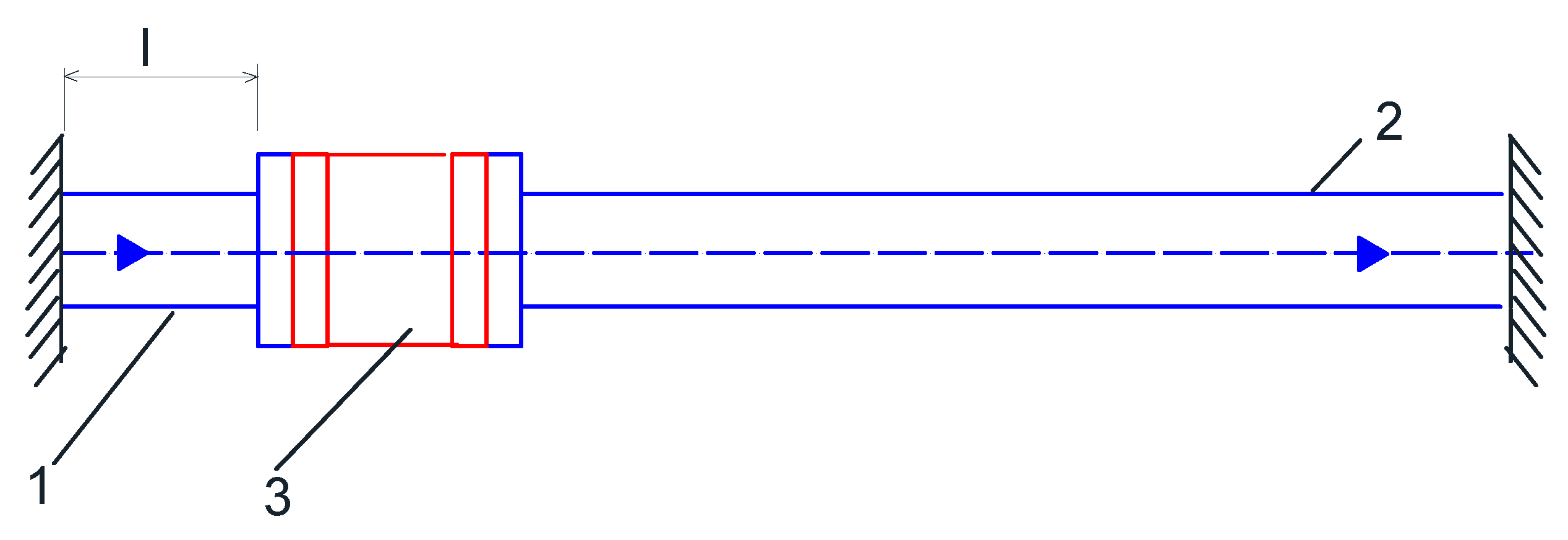
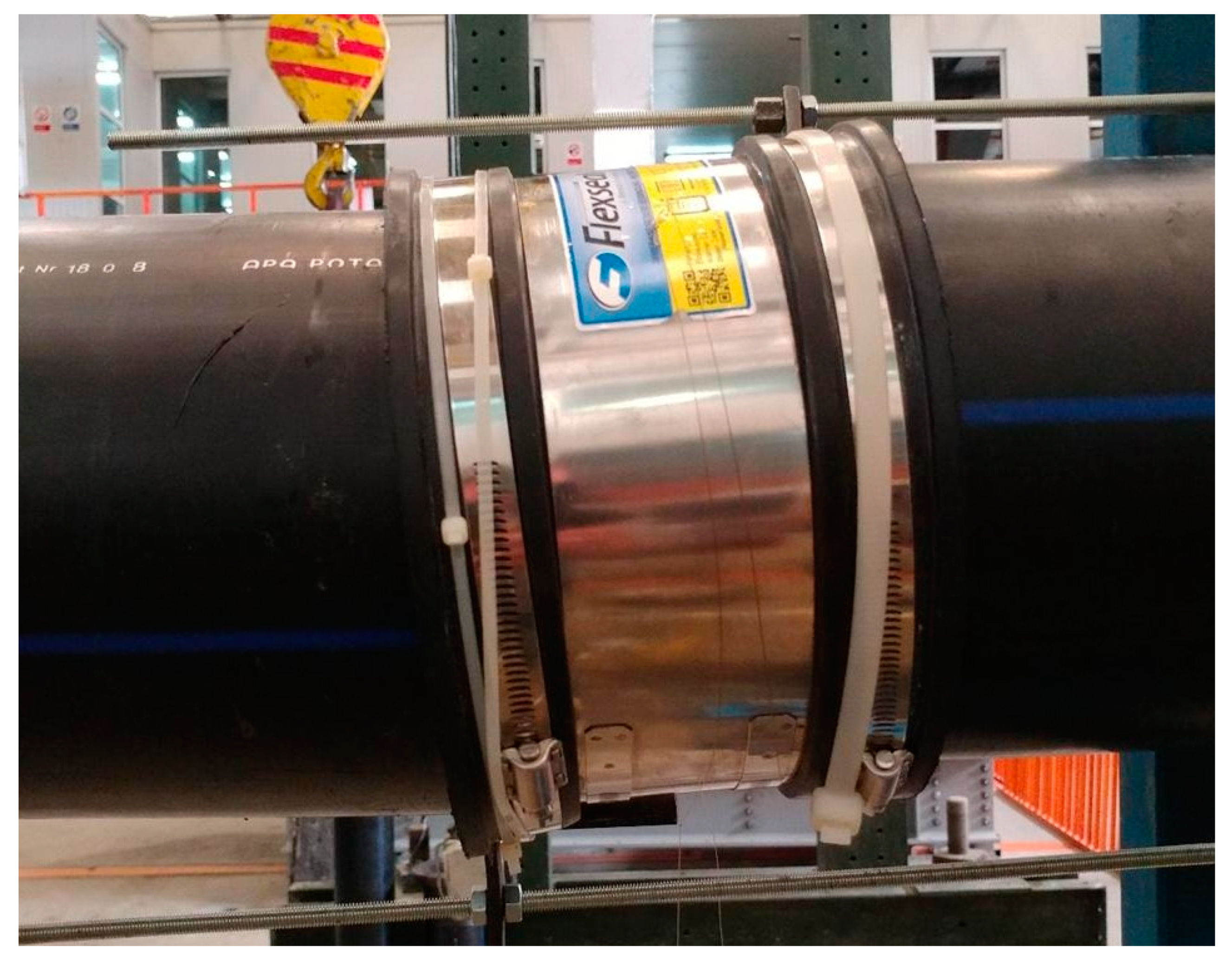
The experimental design of the seismic safety system is an assembly: The pipeline section has flexible reinforcement, consisting of two HDPE200 pipe segments joined by a Flexseal SC200 flexible piece (Figure 1).
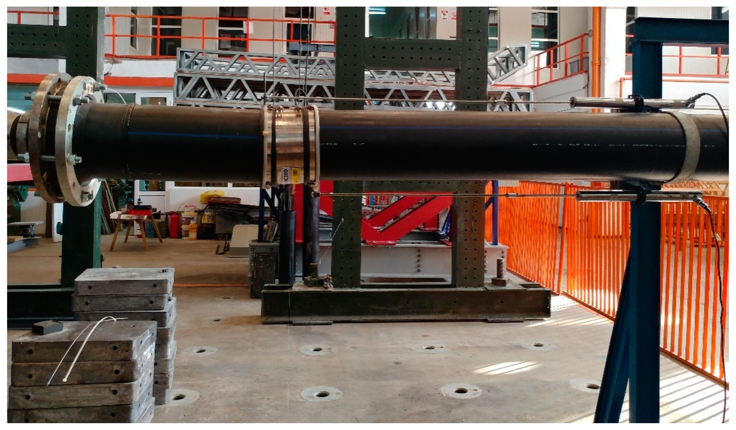
The three pipeline sections of different lengths (500 m, 1000 mm and 1500 mm) were connected via the Flexseal SC200 reinforcement to a pipeline section fixed to a stand whose displacements and rotations were blocked in all three directions to simulate the end points of support of the system (Figure 3).
It is subjected to horizontal actions applied along the axis of the pipeline in order to simulate the effects of a seismic action to which the system may be subjected during its lifetime. The purpose is to determine the optimal distance of mounting such a flexible reinforcement relative to a building (manhole, manifold, etc.) so that the deformations of the workpiece are as small as possible in the case of an earthquake and the change in the alignment of the two pipeline sections be as minor as possible. Thus, conclusions can be drawn regarding the behaviour of the assembly to seismic actions.
The measurements were carried out in the test hall of the Faculty of Civil Engineering and Installations within the ʺGh. Asachiʺ Technical University of Iaşi, duly equipped for tests of this type: Seismic platform, horizontal actuator, etc.
The different length sections were connected via a flange by a horizontal actuator with a capacity of 600 kN. An AEP Transducers force cell with a capacity of 100 kN (Figure 4) was mounted at the end of the actuator in order to measure and record the horizontal force applied to the assembly in Figure 3. The lateral pushing force was transmitted to the assembly by means of a joint which, in addition to the protective role of the equipment used, also had the role of simulating any rotation that may occur in a construction structure in the event of an earthquake.
The horizontal displacement produced by the actuator was monitored by means of a Celesco PT5AV wire displacement transducer (Figure 4). Thus, along with the force-value records, force-displacement curves can be obtained as input parameters for assessing the response of the system formed by the two pipeline sections and the flexible piece.
For the measurement of the linear and angular deformations at the end points of the Flexseal SC200 junction, inductive displacement transducers (LVDTs) were mounted on a rigid frame (Figure 3). Thus, it was possible to measure the relative displacements between the two ends of the flexible joint.
Experimental data was recorded using an ESAM Traveller CF acquisition system with 64 recording channels. The sampling rate was set to 10 records per second per channel for both the displacement transducers and the force cell.
As previously mentioned, the assembly of two pipeline sections connected by a connection sleeve (Flexseal SC200) was subjected to lateral pushing forces (parallel to the pipe axis) in order to simulate the effects of a seismic motion. The most unfavourable hypothesis was considered, namely: Pipeline sections are partly in a console because of the conditions in the field, e.g., earth compaction, where some pipe sections end up in consoles (no longer support the medium). Although various measures were taken during the execution of the installation work to ensure the horizontality of the pipe fitting area, situations may arise when, for various reasons (vibration, compaction, water infiltration, etc.), certain pipe portions act as a console and not as a continuous element supported on an elastic environment. This can lead to the loss of alignment of two pipeline sections, especially when the aforementioned phenomenon occurs at a joint.
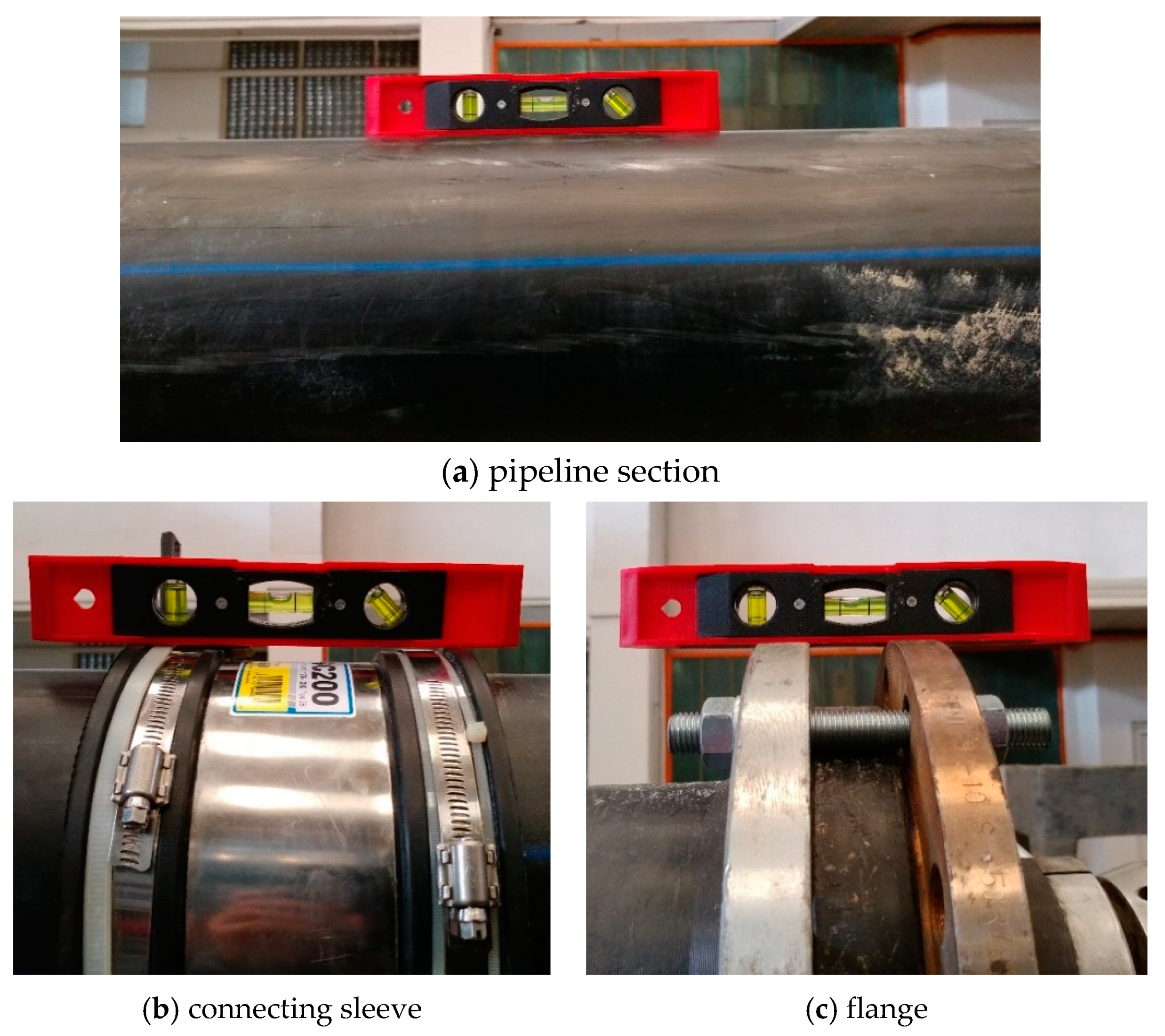
In the assembling phase as well as before each experimental testing, it was envisaged to obtain the horizontality of components of the assembly (Figure 5): The pipeline sections (Figure 5a), the connecting sleeve (Figure 5b), the horizontal load transfer flange (Figure 5c), the rods of the inductive displacement transducers (Figure 3) and the wire of the Celesco PT5AV displacement transducer (Figure 4).
Experimental scenarios have been named to reflect the length of the pipeline section considered directly attached to the building, symbolized by the force cell and the actuator.
In this respect, three experimental scenarios were considered: CG500, CG1000, and CG1500, where C is the pipeline, G is the hollow pipe, and 500 is the length in millimetres of the section attached to the building.
For each scenario, three loading-unloading cycles were applied to achieve a 20 mm relative displacement. At the end of each test, we carried out measurements of the width of the rubber band located inside the Flexseal SC200 which, in addition to the sealing function, also has the role of damping any relative displacements of the two connected pipe ends.
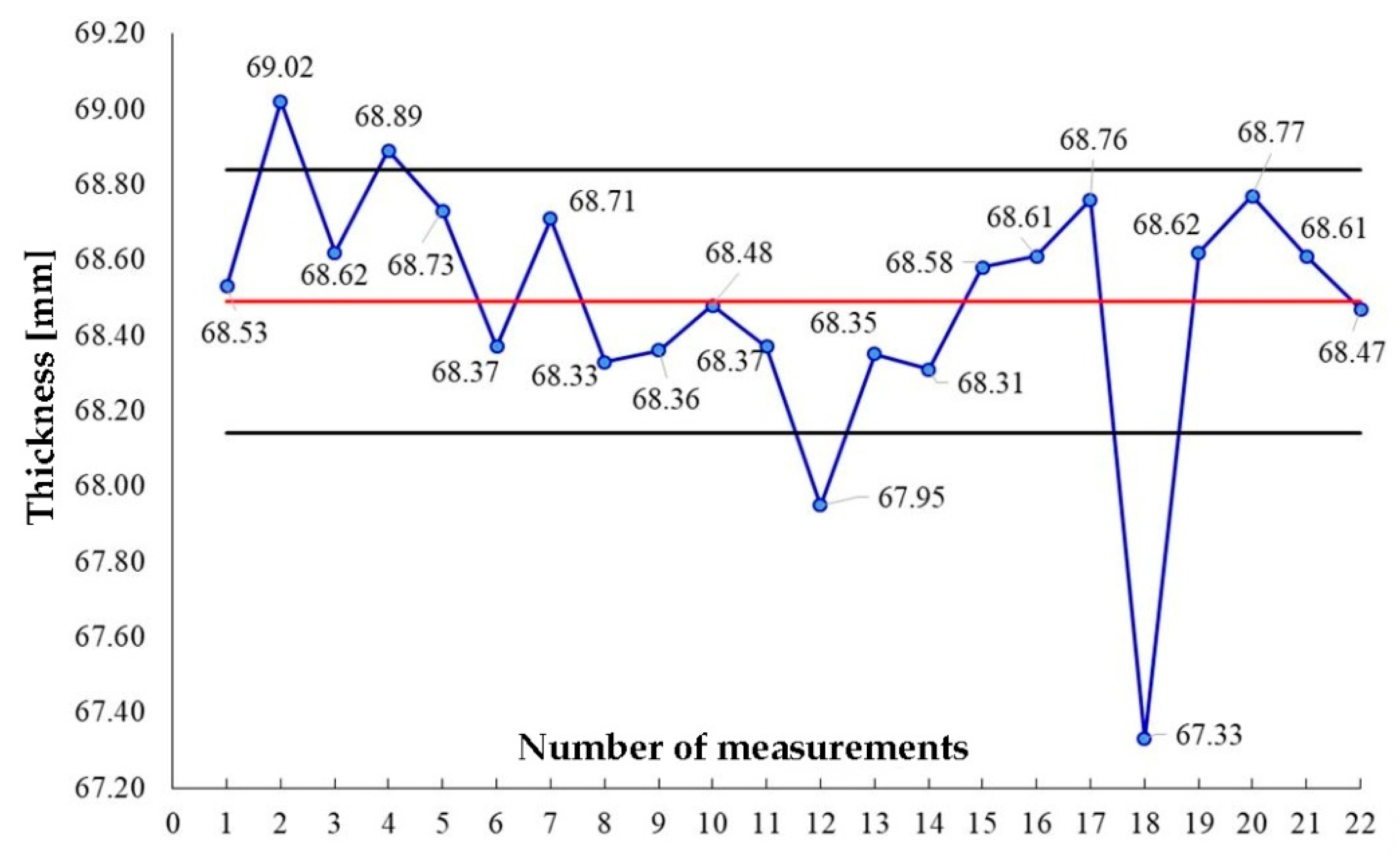
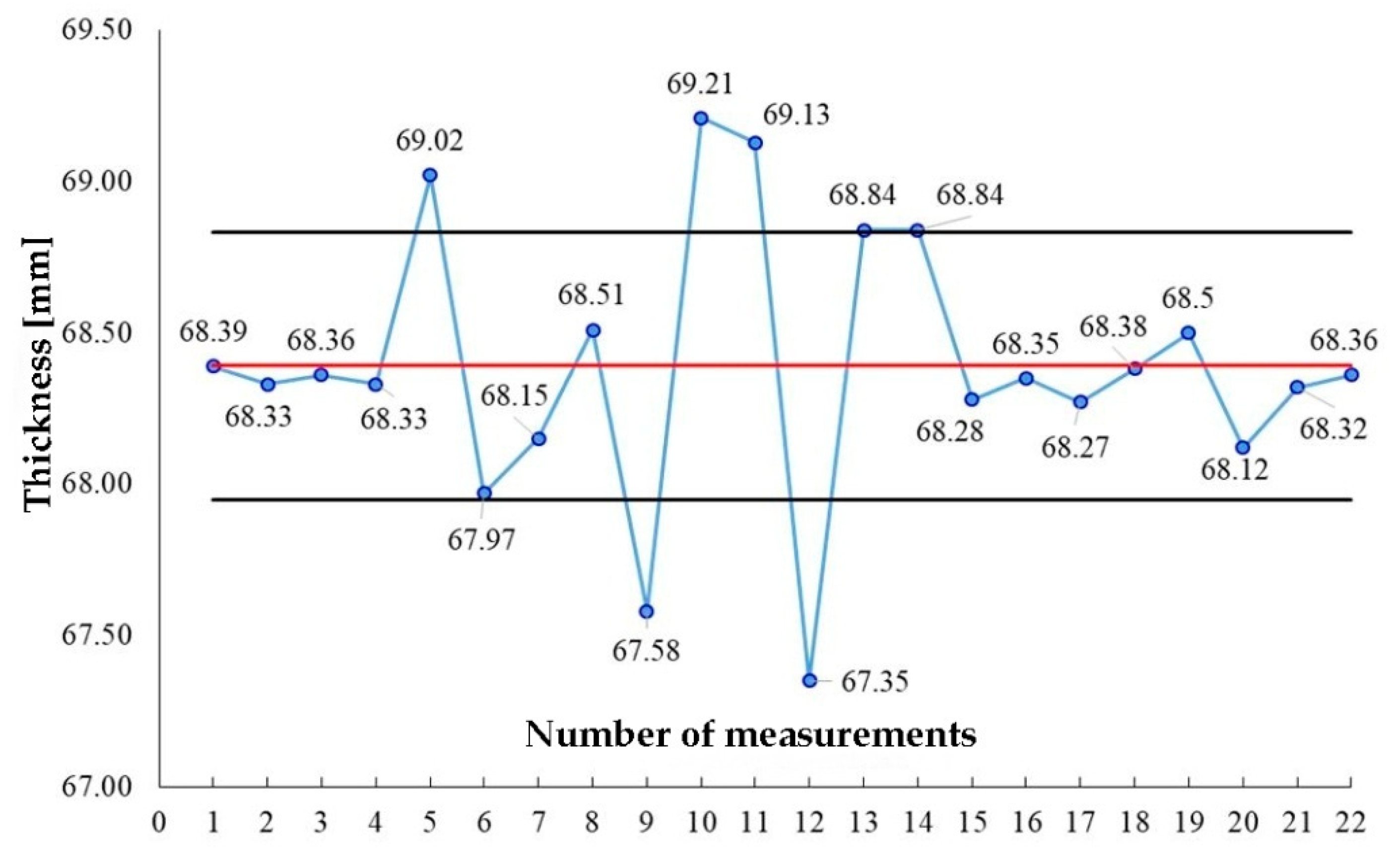
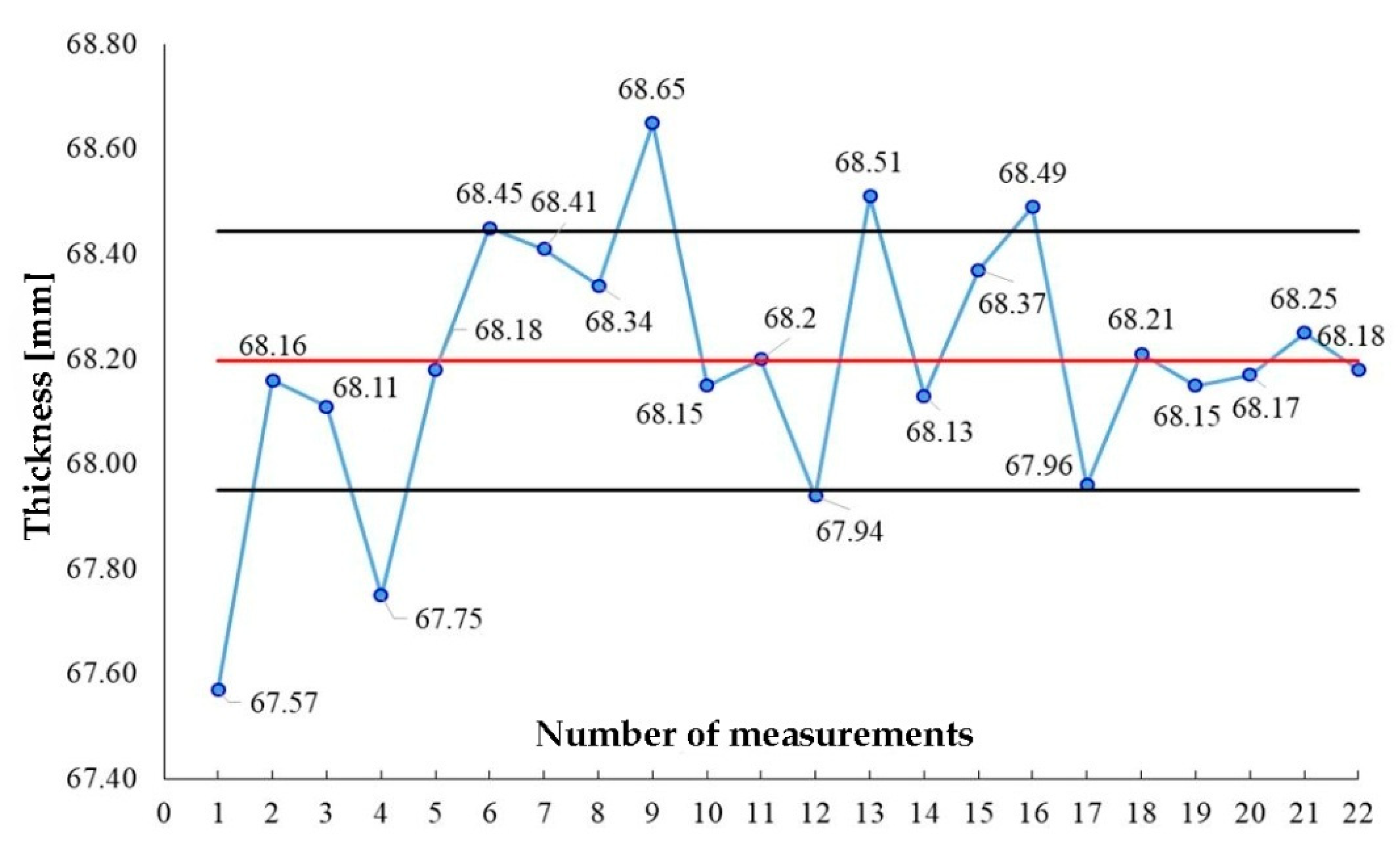
It has been observed that, following the loading-unloading cycles, the rubber band undergoes large residual deformations. For each case, 22 measurements were made over the entire circumference of the rubber band. The results obtained have been statistically processed to eliminate any measurement errors.
3. Results and Discussions
The distribution of measured values for CG500, CG1000 and CG1500 is shown in Figure 6, Figure 7 and Figure 8 and the results were centralized.
As a result of the measurements, it can be noticed that the central rubber band does not suffer any significant changes in width, which indicates that it behaves very well when taking over/damping the relative displacements of the two pipe ends. Also, the variation in thickness at the end of the three scenarios considered is 0.48%, being within the scope of measurement errors or eventual imperfections resulting from the band manufacturing. The second hypothesis is also supported by the graphical presentation of the width variation of the rubber band illustrated in Figure 6, Figure 7 and Figure 8.
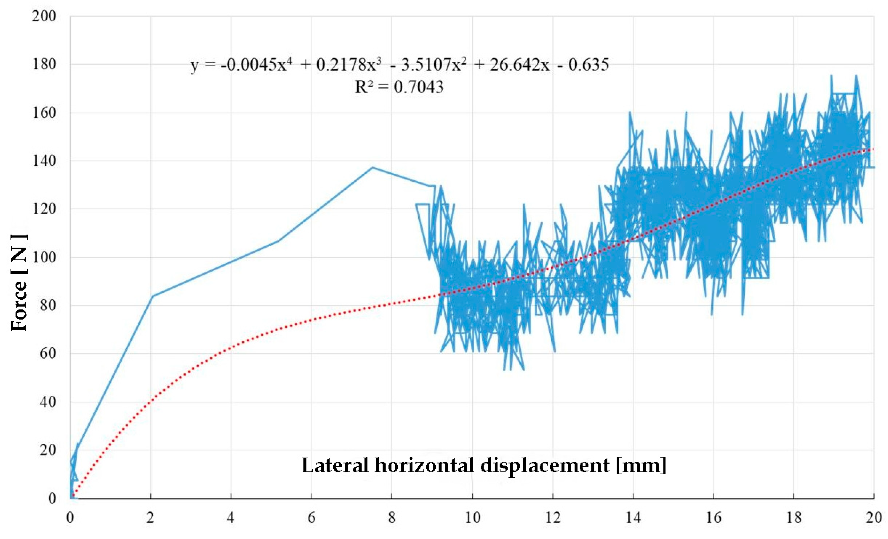
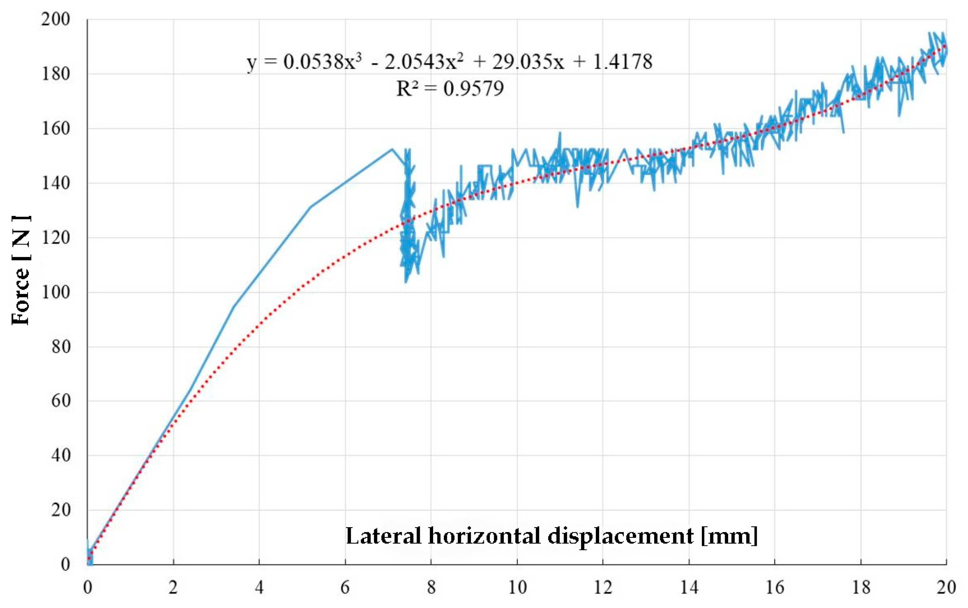
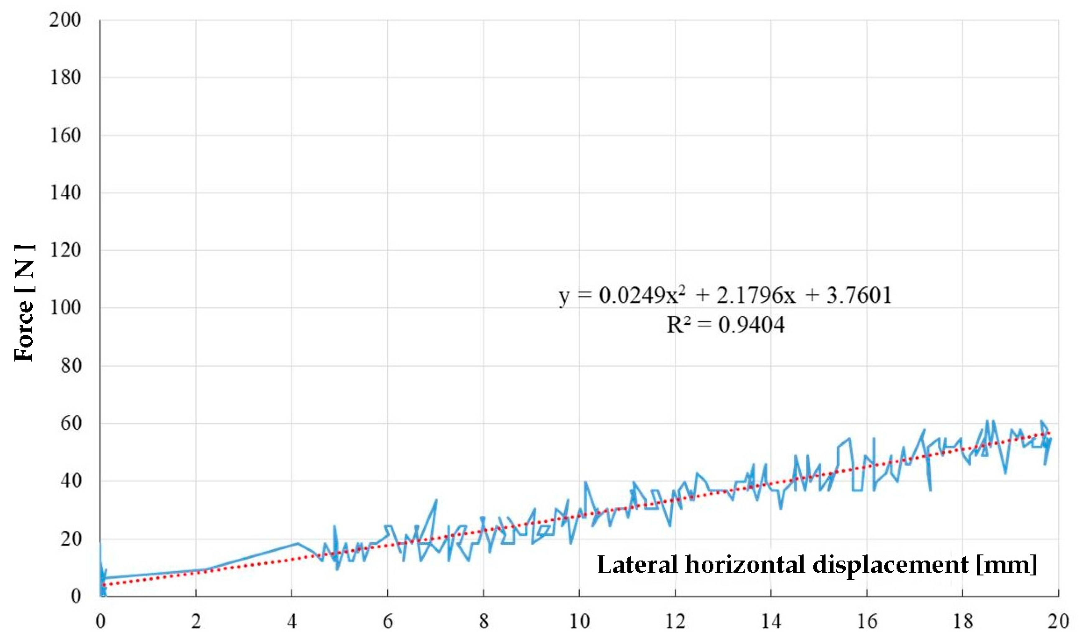
The average force–lateral horizontal displacement curves are shown in Figure 9, Figure 10 and Figure 11. Only the loading level is shown as it is of interest with respect to the maximum applied force and the relative target displacement of 20 mm. Due to the large data sampling resolution, the initial charts are difficult to interpret so that the version of the results presentation as an approximation curve was also chosen. It was intended to obtain an R2 correlation coefficient as large as possible between the approximation curve and the initial chart. For each of the three CG cases, the variant of an approximation curve expressed by a polynomial function was chosen.
It can be noticed that the best correlations between the force–lateral displacement curve and the approximation curve were obtained for CG1000 and CG1500 cases, with a correlation coefficient value above 0.9.
From the charts shown in Figure 9, Figure 10 and Figure 11 it can be seen that initially the lateral displacement increases pro rata with the applied horizontal force. In the range of 4–8 mm, depending on the length of the pipeline section, there is a sudden drop in the value of the applied force, which will gradually increase again until reaching the target displacement of 20 mm.
This sudden drop in the applied force value is due in each of the three cases to the Flexseal SC200 rotation and to the rearrangement of the pipe ends inside the sleeve. The rotation of the sleeve increases gradually until reaching the target lateral displacement, resulting in a continuous rearrangement/repositioning of the two pipe ends. This is evidenced by a more unconventional shape of the force–displacement curves after the 4–8 mm range.
The rotation of the Flexseal SC200 flexible sleeve is shown in Figure 12.
From Table 2, it can be noticed that the central rubber band does not suffer significant changes in width, which indicates that it behaves very well when taking over/damping the relative displacements of the two pipe ends. Also, the variation in thickness at the end of the three scenarios considered is 0.48%, being within the scope of measurement errors or eventual imperfections resulting from the band manufacturing. The second hypothesis is also supported by the graphical presentation of the rubber band width variation illustrated in Figure 6, Figure 7 and Figure 8.
The summary of experimental results on CG scenarios is given in Table 3.
For each scenario considered in the tests, the section of different length, namely CG500 (l = 500 mm), CG1000 (l = 1000 mm) and CG1500 (l = 1500 mm), and the linear (DL) and angular (φ) displacements corresponding to the intensity of the application force (F), were measured.
4. Validation of Experimental Results
In force systems—special groupings—corresponding to the phase of hollow pipe in a dynamic regime [5], it is specified that if the ratio
the water distribution pipeline resists the considered stress.
For the experimental measurements presented in Table 2, we obtained:
For the CG500 system:
For the CG1000 system:
For the CG1500 system:
We notice that for all three different systems, i.e., CG500, CG1000, and CG1500, the ratio Δ ≈ 5%, so for values of test forces superior to those in Table 2, the pipeline will yield.
The CG1000 section works best, in which case the test force may reach the value of: 180 N, see Figure 7.
5. Conclusions
The multitude of possible failures, but especially the avoidance of total decommissioning, requires the observance of measures and recommendations for anti-seismic protection for water networks, such as:
- The provision of expansion sleeves at pipe joints with rigid constructions (tanks, walls, massive anchorage manholes, etc.); and
- The provision of flexible joints located on the straight pathway of the pipeline.
In line with these recommendations stands the research we carried out for a maximally efficient seismic protection system.
In this case, of all three variants, fitting the reinforcement at a distance of 1000 mm. (e.g., a manhole) is the most efficient according to the results in Table 3. The fitting at a distance of 1500 mm leads to damage to the pipe at a lower force equivalent to the ground pushing pressure and therefore a lower seismic intensity.
We mention that the tests were carried out in the most disadvantageous scenario (hollow section and mounted above ground) but this does not in any way affect the actual situation of the water transport pipelines under pressure, fitted and buried, neither in terms of seismic safety nor costs. The junctions tested are used in execution, but mounted randomly, so they are used anyway but are often misplaced.
We can thus define the resilience of pipelines for water supply and distribution, by understanding the seismic shock resistance.
Starting from this research, we want to use the data obtained as a starting point for other experimental studies and we want to lay down binding regulations in the design of water networks to seismic actions.
It is intended to continue the research considering the experimental study of other pipe materials and diameters in order to make a comparative study and to develop general execution procedures.
Author Contributions
Conceptualization, A.D.A. and I.A.; methodology, A.D.A. and I.A.; validation, M.P. and I.T.; formal analysis, I.T.; investigation, A.D.A.; data curation, A.D.A. and I.A.; writing—original draft preparation, A.D.A. and I.T.; visualization, I.A. and M.P.; supervision, M.P.; and project administration, M.P.
Funding
This research was funded by Executive Agency for Higher Education, Research, Development and Innovation Funding, PN III P2 Innovation Cheque 151 CI/2018—Creating and Testing the Experimental Design of a Seismic Protection Assembly for Buried Water Transport Pipelines for its Implementation, https://uefiscdi.ro.
Acknowledgments
Technical support—Seismic Platform, Horizontal Actuator—Technical University “Gheorghe Asachi” of Iasi, Faculty of Construction and Building Services https://eeris.gov.ro/UNIVERSITATEA-TEHNIC-GHEORGH.
Conflicts of Interest
The authors declare no conflict of interest.
References
- Ryu, Y.; Kwag, S.; Ju, B.S. Fragility Assessments of Multi-Story Piping Systems within a Seismically Isolated Low-Rise Building. Sustainability 2018, 10, 3775. [Google Scholar] [CrossRef]
- Meniconi, S.; Brunone, B.; Frisinghelli, M. On the role of minor branches, energy dissipation, and small defects in the transient response of transmission mains. Water 2018, 10, 187. [Google Scholar] [CrossRef]
- Yoo, D.G.; Lee, J.H.; Lee, B.Y. Comparative Study of Hydraulic Simulation Techniques for Water Supply Networks under Earthquake Hazard. Water 2019, 11, 333. [Google Scholar] [CrossRef]
- Bross, L.; Krause, S.; Wannewitz, M.; Stock, E.; Sandholz, S.; Wienand, I. Insecure Security: Emergency Water Supply and Minimum Standards in Countries with a High Supply Reliability. Water 2019, 11, 732. [Google Scholar] [CrossRef]
- Furis, D.; Teodorescu, M.E.; Sorohan, L. Calculul structurilor pentru transportul apei; Conspress: Bucharest, Romania, 2012. [Google Scholar]
- Ancas, A.D.; Profire, M. The Effeects of pH Soil on Mechanical Properties of GRP Pipes. Environ. Eng. Manag. J. 2018, 17, 1879–1885. [Google Scholar] [CrossRef]
- Așchilean, I.; Iliescu, M.; Ciont, N.; Giurca, I. The Unfavourable Impact of Street Traffic on Water Distribution Pipelines. Water 2018, 10, 1086. [Google Scholar] [CrossRef]
- Așchilean, I.; Giurca, I. Choosing a Water Distribution Pipe Rehabilitation Solution Using the Analytical Network Process Method. Water 2018, 10, 484. [Google Scholar]
- Inspectoratul General Pentru Situaţii de Urgenţă. Available online: https://www.igsu.ro/documente/informare_preventiva/ghid_cetatean_SU.pdf (accessed on 12 December 2018).
- Wood, D.J. Influence of line motion on water hammer pressures. J. Hydraul. Div. 1969, 95, 941–959. [Google Scholar]
- Watkins, K.R.; Anderson, R.L. Structural Mechanics of Buried Pipes; CRC Press: Boca Raton, FL, USA, 2000. [Google Scholar]
- Kawashima, K. Seismic Analysis of Underground Structures. J. Disaster Res. 2006, 3, 378–389. [Google Scholar] [CrossRef]
- ASRO (Asociația de Standardizare din România). ASRO-SR EN 1991-1-7:2004 Eurocode 1, Acțiuni asupra structurilor Partea 1–7, Acțiuni generale—Acțiuni accidentale (Eurocode 1, Actions on Structures, Part 1–7, General Actions—Accidental Actions); ASRO (Asociația de Standardizare din România): Bucuresti, Romania, 2004. [Google Scholar]
- Ancaș, A.D.; Atanasiu, G.M. Seismic Risk Management considering the Urban Lifeline Existing System, Business Excellence vol. I. In Proceedings of the 6th International Conference on Business Excellence, Braşov, Romania, 14–15 October 2011; Constantin Brătianu Publishing House: Braşov, Romania, 2011; pp. 20–23, ISBN 978-973-598-939-2. Available online: http://apps.webofknowledge.com (accessed on 18 May 2019).
- Moser, A.P. Buried Pipe Design, 2nd ed.; McGraw Hill: New York, NY, USA, 2001. [Google Scholar]
- Negoiță, A.; Bălan, F.; Brabăn, V.; Budescu, M.; Dabija, F.; Florea, S.; Hobjilă, V.; Pop, I.; Scharf, F.I. Inginerie seismcă; Editura Didactică şi Pedagogică (E.D.P.): Bucharest, Romania, 1985. [Google Scholar]
- ASRO (Asociația de Standardizare din România). ASRO-SR EN 1998-1.2004 Eurocode 8. Proiectarea structurilor pentru rezistență la cutremur. Partea 4. Silozuri, rezervoare și conducte (Eurocode 8. Design of Structures for Earthquake Resistance. Part 4. Silos, Tanks and Pipes); ASRO (Asociația de Standardizare din România): Bucuresti, Romania, 2004. [Google Scholar]
Figure 1.
Experimental design. (1) High density polyethylene pipeline section (HDPE200) of l = 500 mm, 1000 mm and 1500 mm; (2) HDPE pipeline section of any length; and (3) the coupling piece (Flexseal Couplings SC200 reinforcement (Figure 2)).
Figure 1.
Experimental design. (1) High density polyethylene pipeline section (HDPE200) of l = 500 mm, 1000 mm and 1500 mm; (2) HDPE pipeline section of any length; and (3) the coupling piece (Flexseal Couplings SC200 reinforcement (Figure 2)).

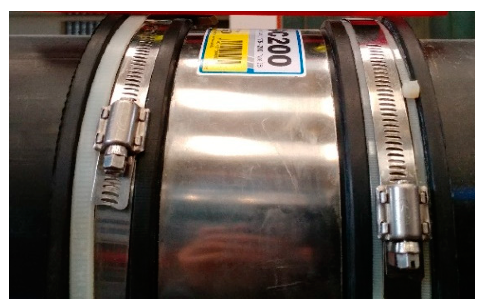
Figure 2.
Flexseal Couplings SC200 reinforcement.

Figure 3.
System consisting of two pipeline sections joined by a Flexseal SC200.

Figure 4.
AEP 100 kN Force Cell and Celesco PT5AV wire displacement transducer.

Figure 5.
Horizontality of the system components.

Figure 6.
Inner rubber band width variance for CG500.

Figure 7.
Inner rubber band width variance for CG1000.

Figure 8.
Inner rubber band width variance for CG1500.

Figure 9.
Force–displacement chart and approximation curve for CG500.

Figure 10.
Force–displacement chart and approximation curve for CG1000.

Figure 11.
Force–displacement chart and approximation curve for CG1500.

Figure 12.
Flexible sleeve rotation during experimental testing for CG scenarios.


Table 1.
Mechanical and elastic features of high-density polyethylene (HDPE) material.
| Material Type | Outer Diameter D (mm) | Wall Thickness t (mm) | Longitudinal Elasticity Module E (MPa) | Transversal Elasticity Module G (MPa) | Poisson’s Coefficient (μ) | Specific Weight (kN/m2) | Flow Limit (mPa) |
|---|---|---|---|---|---|---|---|
| HDPE200 | 200 | 11.9 | 700 | 310 | 0.42 | 9.5 | 25 |
Table 2.
Centralization of measurements for the central rubber band width.
| Scenario. | Measured Values | Average Value (mm) | Standard Deviation | Values Considered | Final Average Value (mm) |
|---|---|---|---|---|---|
| CG500 | 22 | 68.49 | 0.35 | 18 | 68.53 |
| CG1000 | 22 | 68.39 | 0.44 | 15 | 68.31 |
| CG1500 | 22 | 68.20 | 0.25 | 15 | 68.20 |
Table 3.
Centralization of experimental results for CG scenarios.
| Scenario | Target Lateral Displacement, DL (mm) | Associated Duly Force F (N) | R2 Correlation Coefficient | Maximum Rotation Angle (°) |
|---|---|---|---|---|
| CG500 | 20.02 | 175.41 | 0.7043 | 1.239 |
| CG1000 | 20.10 | 195.24 | 0.9579 | 2.562 |
| CG1500 | 19.83 | 122.02 | 0.9404 | 2.902 |
© 2019 by the authors. Licensee MDPI, Basel, Switzerland. This article is an open access article distributed under the terms and conditions of the Creative Commons Attribution (CC BY) license (http://creativecommons.org/licenses/by/4.0/).
Share and Cite
MDPI and ACS Style
Ancaş, A.D.; Aşchilean, I.; Profire, M.; Toma, I. System for Increasing the Seismic Safety of Pipelines in the Water Supply and Distribution Networks. Water 2019, 11, 1049. https://doi.org/10.3390/w11051049
AMA Style
Ancaş AD, Aşchilean I, Profire M, Toma I. System for Increasing the Seismic Safety of Pipelines in the Water Supply and Distribution Networks. Water. 2019; 11(5):1049. https://doi.org/10.3390/w11051049
Chicago/Turabian StyleAncaş, Ana Diana, Ioan Aşchilean, Mihai Profire, and Ionuţ Toma. 2019. "System for Increasing the Seismic Safety of Pipelines in the Water Supply and Distribution Networks" Water 11, no. 5: 1049. https://doi.org/10.3390/w11051049
Note that from the first issue of 2016, this journal uses article numbers instead of page numbers. See further details here.