Reflection Phenomena in Underground Pumped Storage Reservoirs


Institute of Hydraulic Engineering and Water Resources Management, RWTH Aachen University, 52062 Aachen, Germany
*
Author to whom correspondence should be addressed.
Water 2018, 10(4), 504; https://doi.org/10.3390/w10040504
Submission received: 21 February 2018
/
Revised: 10 April 2018
/
Accepted: 16 April 2018
/
Published: 19 April 2018
(This article belongs to the Special Issue Planning and Operations of Multi-Objective River and Reservoir Systems)
Abstract
:Energy storage through hydropower leads to free surface water waves in the connected reservoirs. The reason for this is the movement of water between reservoirs at different elevations, which is necessary for electrical energy storage. Currently, the expansion of renewable energies requires the development of fast and flexible energy storage systems, of which classical pumped storage plants are the only technically proven and cost-effective technology and are the most used. Instead of classical pumped storage plants, where reservoirs are located on the surface, underground pumped storage plants with subsurface reservoirs could be an alternative. They are independent of topography and have a low surface area requirement. This can be a great advantage for energy storage expansion in case of environmental issues, residents’ concerns and an unusable terrain surface. However, the reservoirs of underground pumped storage plants differ in design from classical ones for stability and space reasons. The hydraulic design is essential to ensure their satisfactory hydraulic performance. The paper presents a hybrid model study, which is defined here as a combination of physical and numerical modelling to use the advantages and to compensate for the disadvantages of the respective methods. It shows the analysis of waves in ventilated underground reservoir systems with a great length to height ratio, considering new operational aspects from energy supply systems with a great percentage of renewable energies. The multifaceted and narrow design of the reservoirs leads to complex free surface flows; for example, undular and breaking bores arise. The results show excessive wave heights through wave reflections, caused by the impermeable reservoir boundaries. Hence, their knowledge is essential for a successful operational and constructive design of the reservoirs.
1. Introduction
Nowadays, pumped storage plants are the only technically proven and cost-effective energy storage technology and are the most used [1,2]. In case of a surplus of electrical energy, pumps move water from a lower reservoir to an upper reservoir, where it is saved in the form of potential energy. In case of electrical energy demand, the water flows inversely; through energy conversion, the machines generate electrical energy. At present, the reservoirs used can be rivers, natural or artificial lakes or the ocean. For the height design of the reservoirs, a calculated freeboard avoids overtopping. It consists of the maximum wave height, which depends on the occurring wind and the reservoir design, and a safety margin [3]. In addition, research into the effects of hydropeaking is ongoing [4].
Currently, very little expansion of pumped storage plants occurs, especially in Germany [5]. The main reasons for this are site limitations and environmental aspects [5]. It is not clear why the expansion is nearly stagnant whereas the world needs a lot more energy storage in the future due to the expansion of renewable energies. Research into alternative storage systems is also ongoing [6].
However, underground pumped storage plants could be one alternative. They would work on the same principle as classical plants, but the design of the underground reservoirs would have to be different for stability reasons in the subsurface [7]. Either existing cavities or new cavities are possible. In both cases and for economic reasons the ratio between water and reservoir volume should be as small as possible and fast operational changes should be possible. It is not likely that we can plan and realize those plants without new construction rules, which require exact knowledge of the hydrodynamic processes. The calculation of the freeboard is different from that in classical plants. The wave types differ and air waves arise through ventilation instead of wind. In addition, the effect of failure is different; if the freeboard height is too low, instead of wave overtopping in classical plants, the waves would touch the top with dangerous pressure shocks resulting. If the reservoir system has a high length to height ratio, the ventilated channels are often branched; therefore, many different design ideas exist [7,8,9].
The wave types in underground pumped storage reservoirs are undular bores, undular bores with secondary waves and breaking bores [10]. An overview of the specific behaviour, depending on operation and geometry, is provided by Schüttrumpf and Pummer (2014) [11].
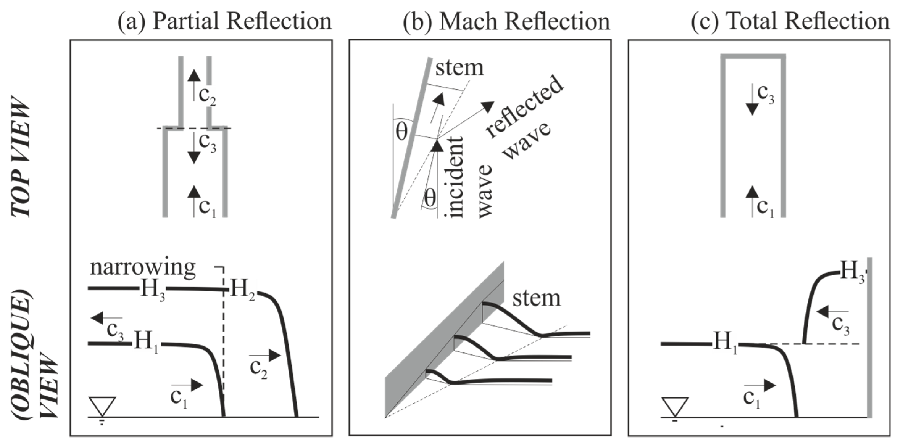
The aim here is the analysis of the appearing wave reflections in underground pumped storage reservoirs. It is important to know the wave height, the wave velocity and the reservoir damping time for successful operational and constructive design. Reflections arise through profile changes in open channel flows and the waves can get an exceptionally strong magnitude. Here, the focus is on three possible types of reflections (Figure 1). By profile discontinuity, every shock wave in an open-channel flow changes its wave height and reflects partially (Figure 1a) [12]. Superposition of shock waves occurs if waves with a different flow velocity run in the same direction, or if opposed waves transmit each other. Mach-stems with reflection arise if the angle ϴ of the incident wave to the wall is between 20° and 45° (Figure 1b). If the angle is smaller than 20°, the Mach-stem arises without reflection. Larger angles than 45° lead to regular reflections. At channel ends, the wave reflects totally, as shown in Figure 1c. The following sections describe these types in detail.
Field measurements, physical model tests and numerical simulations in various levels of complexity exist for the analysis of the hydrodynamic processes in classical pumped storage plants [4,15,16]. Mostly in coastal engineering, successful physical and numerical modelling was carried out to analyse wave reflections [17,18,19]. Depending on the complexity of the expected data, a combination of these methods takes place. Owing to the expense and the methodological difficulty, hybrid modelling usually only addresses the analysis of complex hydrodynamic processes. Very few studies have addressed hydrodynamic processes in underground pumped storage plants. If so, the studies were carried out at a low level [9]. This is the first study using hybrid modelling as a combination of physical and numerical 3D modelling for the analysis of the hydrodynamic processes in ventilated underground pumped storage reservoirs with a high length to height ratio. Two physical models give the basics of the flow processes. The fast, effective execution allows for fast operational changes. The models are equipped with mature contactless measurement instruments. The 3D numerical OpenFOAM modelling addresses constructive changes and the high data density gives results for all relevant points in the model. The models provided a time- and cost-saving analysis, which allows for the exact identification of wave types. The results allow for the improvement of design concepts or the verification of existing designs.
2. Theory
2.1. Partial Reflection
Profile discontinuity through a change in channel width and channel height (slope) results in partial reflections. Profile narrowing results in an increase of the transmitted shock wave (Figure 1a, Section 1); the reflected wave is nearly equal to the initial wave. In contrast, profile expansion reduces the wave height and the reflected wave is from the opposite type. For example, positive surge waves change into negative ones. In the event of channel expansion through height, the wave velocity increases and the wave height decreases. On the other hand, an expansion of the channel width leads to smaller wave velocities and heights. In analogy, this happens for profile narrowing.
To calculate the wave height of the reflected wave (H2), Frank (1957) and Chow (1959) give the following formula for abrupt profile changes [16,20]. Figure 1a (Section 1) shows the respective variables.
Given that acceleration and delay height are negligible, the sum of the continuing wave height (H2) must equal the sum of initial (H1) and reflected wave height (H3), and the continuity equation applies. Through the combination of equations, the calculation of the reflected wave height (H2) is possible. For that, the initial wave height (H1) is multiplied by the difference of the product of initial wave velocity (c1) and initial channel width (b1) and wave velocity (c3) and channel width after profile discontinuity (b3) divided by the difference of the product of wave velocity and channel width from the returning (b2)(c2) and the continuing (b3)(c3) wave. As many variables are required, simplified formulas also exist, for example in Krey (1923) and Forchheimer (1924) [21,22]. For gradual profile changes, see also Forchheimer (1924) [22].
2.2. Mach Reflection
The so-called Mach reflection represents a special case of reflection on vertical walls. It describes the impingement and reflection of waves with an angle of incidence (θ) smaller than 45° to the vertical wall. The special aspect is that the wave does not leave the wall completely after impinging it. Near the wall, a wave load (stem) is formed (Figure 1b, Section 1). Perroud (1957) proved a stem angle of 1° for an angle of wave incidence of 45° [23]. According to studies from Berger and Kohlhase (1976), the stem height can reach twice the height of the incoming wave and is therefore even greater than the classical total reflection [12] (see Section 2.3). The position of the maximum height depends on the wave’s angle of incidence. At angles smaller than 20°, only the Mach reflection arises, whereas at angles greater than 20° and smaller than 45° the Mach reflection and the classical reflection are present.
2.3. Total Reflection
Figure 1c (Section 1) shows the total wave reflection on a vertical wall in the top and side view. To calculate the wave height of the reflected wave (H3) Frank (1957) gives the following equation [16,20]:
The returning wave velocity (c2) and the channel with (b2) are zero, so that Equation (1) reduces to Equation (2). The wave height after reflection (H2) nearly doubles through the resulting superimposition.
3. Method
3.1. Experimental Setup
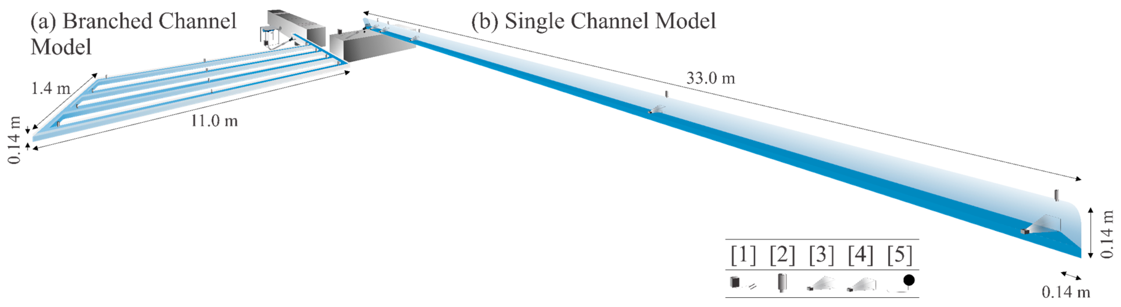
The physical models described herein are unique and specifically designed for the analysis of the flow patterns in underground pumped storage reservoirs. Figure 2 shows the design of the branched channel model (a) and the single channel model (b). Both systems could be either the upper or the lower reservoir in underground pumped storage plants.
The branched channel model (a) is made of concrete and the channels have a height of 0.14 m, without a top cover (Figure 3). Each of the four channels is 11 m long and 0.1 m wide and connected with the inflow channel at an angle of 45°. A pump provides the inflow, and moves the water from a tank into the system. The outflow works through gravity. Electric valves regulate the inflow and outflow. The number of the channels and the operational factors are variable. Table 1 shows the measurement equipment for water levels, velocity, and discharge. To show the positions, the numbers for the measurement equipment in Table 1 are equivalent to the numbers in Figure 2.
The single channel model (b) is made of Plexiglas, closed and ventilated (Figure 3). It has a length of 33 m to ensure an equal area of both models with the aim of a reasonable comparison. The model has PIV and LDA instrumentation for velocity measurements and pressure transmitters for pressure measurements in addition to the branched channel model (a) (Figure 2, Table 1).
With those models, the fundamental design parameters are covered. The variated operational parameters are the duration of opening and closing the valves, the discharge, and the initial and final water levels. For the constructive parameter study, the ground area and the inlet and outlet design, as well as the branch angles, are constant for the reason of comparability. The variated constructive parameters are the number of branches, the channel length, the cross area, the slope, and the roughness.
3.2. Numerical Setup
This paper describes a 3D numerical simulation, using the software OpenFOAM for the analysis of the hydrodynamic processes in the underground pumped storage reservoirs. The present method is based on a finite-volume approach, whereby the partial differential equations are calculated in discrete control volumes. Hexahedral elements form the block-structured grid from which the volume body is cut out. High quality grids are important, obtaining high accuracy of the surface and volume integrals and gradients. A compromise of sufficiently fine discretization and minimization of cell numbers was found. The results converged to a grid-independent solution. The number of cells differs depending on the geometry between 1 million and 2 million [10]. The reference geometries of the numerical models equal the two described physical models (Section 3.1).
For the time discretization, the investigation period is subdivided into time intervals with time steps of 0.01 s; this was a result of preliminary studies [24]. Start and end times depend on the respective operational variant. Nevertheless, the time steps for complex flow conditions reduce automatically. The first order, bounded, implicit Euler method is applied. The Courant number judges the stability of the temporal discretization and is less than 0.6 to ensure a stable solution [25].
The free surface flow is calculated by the Reynolds-averaged and Navier–Stokes (RANS) equations. Due to the near-isotropic turbulence, the standard k-Ɛ model is used [26]. Therefore, the simulation is associated with a high degree of simplification, since the average values of the flow variables are calculated. That leads to considerably lower computational effort. The degree of simplification of this method is appropriate, because the results are sufficiently precise in that case [26]. The solver interFoam as a solver for two-phase flows using the algebraic volume-of-fluid method is used. For this purpose, a new scalar field is introduced that is referred to as alpha1 or alphawater. In this case, a distinction is made between the two phases, water and air. The iterative solution strategy within the PIMPLE algorithm solves nonlinearities in the equations and the calculation of pressure. This is a combination of the SIMPLE (Semi-Implicit Method for Pressure-Linked Equations) and the PISO (Pressure-Implicit with Splitting of Operators) algorithms [27].
The initial water level is set as the initial condition and the discharge at the inlet and outlet is set with a determined velocity as the boundary condition [10]. The reference operation mode is a discharge of 1 L/s, filling and emptying starting from an initial water level of 0.02 m and 0.10 m.
3.3. Hybrid Setup
The synergy between the physical modelling and the 3D numerical simulations is beneficial due to the different level of complexity. By physical modelling, a consideration of all hydrodynamic processes, a simple change of the operational boundary conditions and fast experimental results were possible. Disadvantages were possible scale effects (Section 3.4), transmission limits, results restricted to specific measurement points and a great effort in geometry changes. Through the fully coupling with the 3D numerical model (scale 1:1, no transmission limits, high data resolution, simple geometry changes) the disadvantages of the models compensate each other. Therefore, hybrid modelling avoids spatial and temporal model boundaries. The disadvantage of the 3D numerical model is the high computer performance necessary and the long duration for the calculation, due to the complex flow processes arising [11]. Regardless of model limitations, operational and constructive variants are possible after validation within the framework of hybrid modelling. Primarily, the physical model contains the analysis of the effect of operational changes on waves, and the numerical model the analysis of the effect of complex design changes.
The prerequisite is that the hydrodynamic processes in both models match. As proof of the conformity of the hydrodynamic processes, a comparison between water levels and flow velocities at 13 measurement points in the branched channel model and at four measurement points in the single channel model showed deviation less than 4% [10,26].
3.4. Model and Scale Effects
It is necessary to discuss model effects to determine the correctness and transferability of the results. The physical and 3D numerical model results for water levels and flow velocities agree qualitatively and quantitatively; nevertheless, they exhibit model effects. The models reproduce the hydrodynamic processes in the potential underground pumped storage reservoirs. The physical model is equipped with contactless measurement gauges, with the exception of vane anemometers. As a result, the flow processes are not disturbed. The measurement gauges require calibration before every experiment, to ensure correct results. Anyway, the measured data are the mean values of the output data.
Numerical model effects result through the identification and selection of the physical processes, their mathematical formulation and their numerical implementation. The model sections are large enough that the boundaries do not affect the results. Additional simulations checked the RANS simulation and the volume-of-fluid method. Therefore, a 2D simulation with the software TELEMAC2D, using the 2D shallow water equations and solving the water level directly showed useful results [28]. In addition, the results from a 3D simulation with the software DualSPHysics are comparable. The simulation uses the Lagrange method as a different numerical method. Smoothed Particle Hydrodynamics (SPH) was successfully used for the analysis of wave heights and velocities of wave reflections [18,19].
Scale effects result from the violation or insufficient fulfilment of the significant similarity laws in the scale model. There is no benchmark plant for the present model. However, even if the plants should have substantially larger dimensions, it is still possible to use the results of the model tests. Due to the predominance of gravitational and inertial forces in the free surface flow case, Froude’s law does apply, whereby frictional, capillary and elastic forces would be negligible. However, viscous effects characterize the degradation behaviour of undular and breaking bores, which makes the application of Froude’s law not necessarily useful. Leng and Chanson (2015) showed a small effect on water level and wave length by changing the Reynolds number in individual waves compared to the case of a series of turbulent waves in which the specific Froude number is substantially greater [17]. The results of the 3D OpenFOAM numerical model for other dimensions (scale 1:10 and 1:100) showed negligible deviations. Special attention was paid to roughness and surface tension [26].
4. Case Study Description
The hybrid model study identifies the reflection phenomena in underground pumped storage reservoirs by analysing flow velocities and wave heights at the relevant points. Figure 4 shows schematically the wave reflection points in a top view of the models. In the branched system (a), the angle between the channels is set to 45° to test the maximum possible angle for Mach reflections (see Section 2.2). At the end of the channel system, the possible Mach reflection could superimpose the total reflection. In the single-channel model (b), no Mach reflections should occur and the partial reflection from the inflow as well as the total reflection at the end of the channel should correspond to the classical theory (Section 2.3).
For investigating the different wave reflection of diverse wave types, a change of operation modes is necessary in addition to the geometrical changes. Thus, waves of different kinds and magnitude arise [11]. Table 2 shows the tested discharges (Q) and initial water levels (h0) for each model, which were specified on the basis of classical pumped storage plants and designed for future changes in the energy supply system [26].
5. Results
5.1. Overview
Waves arise through the change of discharge, which can be fast in the described pumped storage plants. Their magnitude and type depend in addition on the specific design of the reservoirs. A decisive role is played, for example, by the channel length and width, the number of branches and their angles, direction changes, the slope and the roughness [26]. This section shows the results of the hybrid modelling of different operational and geometrical variants, with a primary focus on the reflection of waves. The focus of the results is the reflections caused by the inflow. The reason for this is that the outflow shows very few reflection issues. The partial reflections in the system occur here through the slope and the changes in channel width. Their extension is significantly smaller here than the extension of Mach and total reflection. Hence, the primary focus is on those types. We include a description of the phenomena of Mach reflection, followed by the total reflection. The following sections present the reflection types and their impact on the reservoir damping.
5.2. Mach Reflection
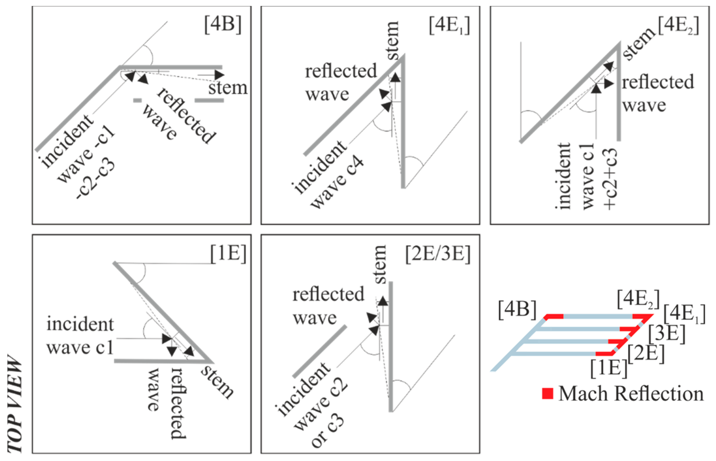
The relevant points for Mach reflections before backflow are shown in Figure 5. In these five positions, the angle between the channels is 45°. This is particular on the one hand, but on the other hand realistic for underground pumped storage reservoirs.
The position in the beginning of channel 4 [4B] shows the first time step of a classical Mach reflection (Figure 5). In detail, Figure 6 shows the 3D numerical results for the ratio between the actual water level (h1) and the initial water level (h0) for the reflection in the inflow channel (a) as well as in the beginning of channel 4 (b). The position specifies the ratio of the x- and y-coordinates at the position (X1, Y1) and the starting point (X0, Y0); the slices are located at the channel outside, middle and inside at the time step 4.5 s. The reflected wave reaches the channel wall at a steeper angle than the first wave, caused by the stem. Repeatedly, the wave touches the sidewalls of channel 4. Depending on the discharge and initial water level, the distance until the wave goes straightforward with its original shape differs. For the reference case, the distance is around two meters.
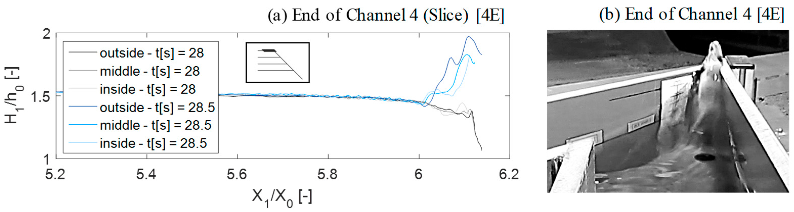
At the end of channel 4, the reflections are complex. Beginning with the Mach reflection [4E1], the wave gets nearly totally reflected at the channel wall and goes back to the opposite wall and so on. In addition, the stem reflects. Depending on the operation, in most cases, the waves from the remaining three channels reach position [4E2] at the same time and additional Mach reflections arise. Repeatedly the reflected waves touch the sidewalls, as well as the stem. In addition, the waves overlap. Figure 7a shows a slice through channel 4 in the outside, the middle and the inside as a result of the 3D numerical OpenFOAM simulation. Before reflection, the relation between wave height and initial water level has a maximum value of 1.45 at the inside and 1.38 at the outside of the channel. After reflection, the relative maximum wave height is 1.98, compared to 1.43 for the initial wave, and not comparable with a classical total reflection anymore. Figure 7b shows a photo of the end of channel 4 [4E], where the waves meet.
The Mach reflection at the end of channel 1 [1E] (Figure 5) is comparable, but of a lower magnitude. The reason is the lower amount of water, which comes just from channel 1 in one direction. Even less prominent are the reflections in the positions at the end of channel 2 [2E] and at the end of channel 3 [3E]; therefore, the details of those cases are not relevant for the consideration of critical points.
5.3. Total Reflection
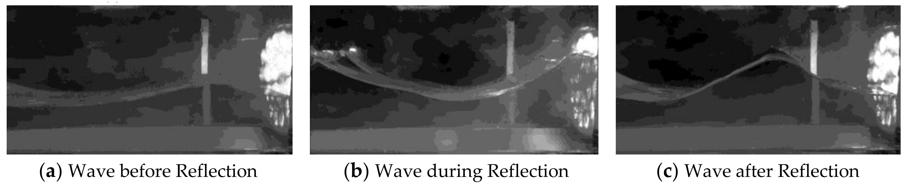
Total reflections occur at the end of the single channel case. Figure 8 shows photos from the channel end of the physical model. The photos show the waves before reflection (a), during reflection (b) and after reflection (c). In theory, the waves double at those positions [15]. Section 3.1 explains the total reflections from previously reflected waves in the branched channel system.
The model results agree well with the theory. Figure 9 shows the ratio of wave height after reflection and initial water level (H2/h0) depending on the ratio of initial wave height and initial water level (H1/h0). The wave heights double approximately through total reflection (see Equation (2), Section 2.3). Total reflections in combination with Mach reflections show higher reflected waves in comparison (Figure 9). The measurement points are at a certain distance from the channel walls. For comparison purposes, the highest local water levels in the edges are not considered.
5.4. Reservoir Damping
The knowledge of the behaviour of the damping process of the reservoirs is essential for a successful plant operation. Strong oscillations prohibit fast operational changes. Equation (3) is used to calculate the mean time-dependent water level (h1/h0) [26]:
The positive inflow (Q) increases the volume of water in the reservoir. For the calculation, the discharge is multiplied by the time (t) and divided by the initial water level (h0), which is multiplied by the ground area (A). Due to the division through the initial water level, the number of 1 must be added. The calculation of the mean ratio of the water level is simple. The great deviation in the local flow processes at certain positions shows the need for more precise calculations. Figure 10 and Figure 11 show the difference between the mean time-dependent relative water level and the measured water level over a dimensionless time factor, which depends on the time (t), the gravity (g) and the initial water level (h0). The respective measurement points are located at the inflow (a), the beginning (b), the middle (c) and the end (d) in both model geometries. In the branched channel model the deflections are frequent (Figure 10), but less pronounced than in the single channel model (Figure 11). The damping process happens more quickly, so that the deviations between measured water levels and mean values become small. The strong reflection processes lead to energy conversions and a quick loss in wave height. The waves reach the inflow point in a significantly shorter time, as in the single channel model.
The results of the single-channel model (Figure 11) show higher deflections over longer periods, for all measurement points. The duration of the flow through the whole reservoir is very long in comparison to the branched-channel model.
6. Discussion
The hybrid model is suitable for the analysis of complex hydrodynamic processes in underground pumped storage reservoirs, which is shown amongst others through the small deviations between the results of physical and numerical modelling (<4%). The results show complex reflection processes at channel branches, direction changes and dead ends. As in theory, the waves nearly double at channel ends through total reflections. At channel branches and direction changes, the reflected wave height can even exceed twice the initial wave height. The damping process is a significant issue intensified by the narrow design, compared to classical pumped storage plants. Even if theoretical considerations about those processes exist, it is necessary to use them correctly for further reservoir design process.
At present, various design guidelines for the freeboard calculation in classical pumped storage plants exist. These guidelines are mostly country-dependent. Germany, for example, uses the DIN 19,700 for freeboard criteria [29]. The U.S. Department of the Interior Bureau of Reclamation has published freeboard criteria and guidelines for computing freeboard allowances for storage dams [30], and additional guidelines exist. Of course, guidelines for underground pumped storage plants do not exist yet; the plants are a new, but very promising concept. If we build the plants in the future, guidelines are indispensable. They should include a freeboard calculation as well as calculation times regarding the operational flexibility of the plant. The results presented here can be used as the basis for the determination of wave heights and wave damping through wave reflections.
7. Conclusions
This paper presents a hybrid model that solves complex hydrodynamic issues in underground pumped storage reservoirs. The hybrid model consists of two physical models in the laboratory of the Institute of Hydraulic Engineering and Water Resources Management at RWTH Aachen University and a 3D OpenFOAM numerical model. To benefit from hybrid modelling, the physical models primarily address all hydrodynamic processes and cover the operational study. The numerical model contains a large amount of data for the constructive study, including scale effects.
Within the aim of evaluating the suitability and performance of underground pumped storage plants, the paper shows criteria for small water levels and fast damping times. For the operational and constructive design, attention to local site conditions is important.
The results show the wave heights for Mach and total reflections and the wave heights and times for the damping process caused by reflections. The hybrid modelling confirms the theoretical considerations for reflections. The angle used for the incident wave of 45° showed Mach reflection with stem waves. According to theory, higher stem waves result from smaller angles, which is relevant in the planning of underground pumped storage reservoirs. On the other hand, the reflections lead to energy conversion and the waves lose their height and move quickly. The damping is relevant for the operational changes, and therefore the flexibility of the plant. It follows that strong reflections are on the one hand undesirable, and on the other hand advantageous. This confirms the influence of the local site-specific aim of the pumped storage plants as a basis for the reservoir design.
The present study shows a strongly underestimated issue about wave heights through reflections. Mach reflections show large extensions and are particularly relevant. Studies of pumped storage plants present various design ideas, in which Mach reflections would occur. However, the studies did not consider them; in general, they did not sufficiently discuss the hydrodynamic processes. Further research could address the interaction of water and the surrounding material, which could be either a lining containing concrete or a naturally occurring material, such as granite. In addition, extensive dimension studies could complement our work. Therefore, a prototype on the 1:1 scale would be a great option.
Acknowledgments
We are indebted to DFG (Deutsche Forschungsgemeinschaft) for providing generous funding for our project.
Author Contributions
Elena Pummer is responsible for the study design, data analysis and text. Holger Schüttrumpf supports the entire process.
Conflicts of Interest
The authors declare no conflict of interest. The founding sponsors had no role in the design of the study; in the collection, analyses, or interpretation of data; in the writing of the manuscript, and in the decision to publish the results.
References
- Chazarra, M.; Pérez-Díaz, J.I.; García-González, J.; Praus, R. Economic viability of pumped-storage power plants participating in the secondary regulation service. Appl. Energy 2018, 216, 224–233. [Google Scholar] [CrossRef]
- Punys, P.; Baublys, R.; Kasiulis, E.; Vaisvila, A.; Pelikan, B.; Steller, J. Assessment of renewable electricity generation by pumped storage power plants in EU Member States. Renew. Sustain. Energy Rev. 2013, 26, 190–200. [Google Scholar] [CrossRef]
- Patt, H.; Gonsowski, P. Wasserbau. Grundlagen, Gestaltung von Wasserbaulichen Bauwerken und Anlagen; Springer-Verlag: Berlin/Heidelberg, Germany, 2011. (In German) [Google Scholar]
- Ibarra, G.; de La Fuente, A.; Contreras, M. Effects of hydropeaking on the hydrodynamics of a stratified reservoir. The Rapel Reservoir case study. J. Hydraul. Res. 2015, 53, 760–772. [Google Scholar] [CrossRef]
- Hartmann, N.; Eltrop, L.; Bauer, N.; Salzer, J.; Schwarz, S.; Schmidt, M. Stromspeicherpotenziale für Deutschland; Institut für Energiewirtschaft und Rationelle Energieanwendung (IER); Institut für Strömungsmechanik und Hydraulische Strömungsmaschinen (IHS); Zentrum für Sonnenenergie- und Wasserstoff-Forschung Baden-Württemberg (ZSW): Stuttgart, Germany, 2012. (In German) [Google Scholar]
- European Commission. Energy Storage—The Role of Electricity; SWD 61; European Commission: Brussels, Belgium, 2018. [Google Scholar]
- Fessenden, R.A. System of Storing Power. U.S. Patent US1247520, 20 November 1917. [Google Scholar]
- Huynen, J. (Ed.) Pumpspeicherwerke im Tiefen Untergrund; EnergieSpeicher. Köln, 17. November; Sogecom Energy Holding BV: Willemstad, Curaçao, 2011. (In German) [Google Scholar]
- Uddin, N. Geotechnical issues in the creation of underground reservoirs for massive energy storage. Proc. IEEE 2012, 100, 484–492. [Google Scholar] [CrossRef]
- Pummer, E.; Schüttrumpf, H. Waves in underground pumped storage plants. In Proceedings of the 85th Annual Meeting of International Commission on Large Dams, Prague, Czech Republic, 3–7 July 2017. [Google Scholar]
- Schüttrumpf, H.; Pummer, E. Unterirdische Pumpspeicherwerke—Eine Alternative? Wasserwirtschaft 2014, 1–2, 70–73. (In German) [Google Scholar] [CrossRef]
- Berger, U.; Kohlhase, S. Mach-Reflexion als Diffraktionsproblem. Die Küste 1977, 31, 139–143. (In German) [Google Scholar]
- Tan, L.-H.; Ren, Y.-X.; Wu, Z.-N. Analytical and numerical study of the near flow field and shape of the Mach stem in steady flows. J. Fluid Mech. 2006, 546, 341–362. [Google Scholar] [CrossRef]
- Ivanov, M.S.; Vandromme, D.; Fomin, V.M.; Kudryavtsev, A.N.; Hadjadj, A.; Khotyanovsky, D.V. Transition between regular and Mach reflection of shock waves: New numerical and experimental results. Shock Waves 2001, 11, 199–207. [Google Scholar] [CrossRef]
- Müller, M.; de Cesare, G.; Schleiss, A.J. Flow field in a reservoir subject to pumped-storage operation—In situ measurement and numerical modeling. J. Appl. Water Eng. Res. 2017, 36, 1–16. [Google Scholar] [CrossRef]
- Frank, J. Nichtstationäre Vorgänge in den Zuleitungs- und Ableitungskanälen von Wasserkraftwerken, 2nd ed.; Springer: Berlin/Göttigen/Heidelberg, Germay, 2017. (In German) [Google Scholar]
- Leng, X.; Chanson, H. Unsteady Turbulence during the Upstream Propagation of Undular and Breaking Tidal Bores: An Experimental Investigation; Report CH98/15; School of Civil Engineering, University of Queensland: Brisbane, Australia, 2015. [Google Scholar]
- Ren, B.; He, M.; Li, Y.; Dong, P. Application of smoothed particle hydrodynamics for modeling the wave-moored floating breakwater interaction. Appl. Ocean Res. 2017, 67, 277–290. [Google Scholar] [CrossRef]
- Amicarelli, A.; Albano, R.; Mirauda, D.; Agate, G.; Sole, A.; Guandalini, R. A smoothed particle hydrodynamics model for 3D solid body transport in free surface flows. Comput. Fluids 2015, 116, 205–228. [Google Scholar] [CrossRef]
- Chow, V.T. Open-Channel Hydraulics; Blackburn Press: Caldwell, NJ, USA, 2009. [Google Scholar]
- Krey, H. Einfluß von künstlichen Querschnittseinengungen auf die Sturmfluthöhe im Tidegebiet der Flüsse; Krey: Berlin, Germany, 1923. (In German) [Google Scholar]
- Forchheimer, P. Wasserschwall und Wassersunk; F. Deuticke: Leipzig, Germany, 1924. (In German) [Google Scholar]
- Perroud, P.H. The Solitary Wave Reflection along a Straight Vertical Wall at Oblique Incidence. Ph.D. Thesis, University of California, Berkeley, CA, USA, January 1958. [Google Scholar]
- Pummer, E.; Cofalla, C.; Schüttrumf, H. Hydrodynamic design development of underground pumped storage caverns—Global flow effects in extreme operating conditions. In Proceedings of the Hydropower & Dams (Hydro 2014), Cernobbio, Italy, 13–15 October 2014. [Google Scholar]
- Laurien, E.; Oertel, H. Numerische Strömungsmechanik. Grundgleichungen und Modelle—Lösungsmethoden—Qualität und Genauigkeit, 5th ed.; Springer Fachmedien Wiesbaden: Wiesbaden, Germany, 2013. (In German) [Google Scholar]
- Pummer, E. Hybride Modellierung der Hydrodynamischen Prozesse in Unterirdischen Pumpspeicherreservoirs. Ph.D. Thesis, Institut für Wasserbau und Wasserwirtschaft, RWTH Aachen University, Aachen, Germany, 2016. (In German). [Google Scholar]
- Maric, T.; Höpken, J.; Mooney, K. The OpenFOAM Technology Primer; Sourceflux: Duisburg, Germany, 2014. [Google Scholar]
- Kreyenschulte, M.; Pummer, E.; Schüttrumpf, H. Analyse der Strömungsprozesse in unterirdischen Tiefspeichern von Pumpspeicherwerken mit Telemac2D. Wasserwirtschaft 2016, 2, 62–67. (In German) [Google Scholar]
- Deutscher Normenausschuss. Fachnormenausschuss Wasserwesen. In Stauanlagensicherheit und Folgen bei der Überschreitung der Bemessungsannahmen nach DIN 19700; DWA-Themen, T1/2017; DWA, Dt. Vereinigung für Wasserwirtschaft, Abwasser und Abfall e.V: Hennef, Germany, 2017. (In German) [Google Scholar]
- U.S. Department of the Interior Bureau of Reclamation. Freeboard Criteria and Guidelines for Computing Freeboard Allowances for Storage Dams; Revised 1992; U.S. Department of the Interior Bureau of Reclamation: Washington, DC, USA, 1981.
Figure 1.
Top view and side/oblique view of partial reflection (a); Mach reflection (b) and total reflection (c) [13,14].

Figure 2.
Drawing of the branched channel model (a) and the single channel model (b).

Figure 3.
Photographs of the branched channel model (a) and the single channel model (b) at the Laboratory of the Institute of Hydraulic Engineering and Water Resources Management at RWTH Aachen University.
Figure 3.
Photographs of the branched channel model (a) and the single channel model (b) at the Laboratory of the Institute of Hydraulic Engineering and Water Resources Management at RWTH Aachen University.

Figure 4.
Wave reflection points in the branched channel system (a) and in the single channel system (b).
Figure 4.
Wave reflection points in the branched channel system (a) and in the single channel system (b).

Figure 5.
Mach reflection points in the branched channel system, before backflow.

Figure 6.
Slice of the inflow channel (a) and channel 4 (b) at the outside, middle and inside, for the time step 4.5 s.
Figure 6.
Slice of the inflow channel (a) and channel 4 (b) at the outside, middle and inside, for the time step 4.5 s.

Figure 7.
Slice of channel 4 (a) at the outside, middle and inside, for the time step 28 s and 28.5 s and photo of the end of channel 4 (b) for the time step 28.5 s in the physical model.
Figure 7.
Slice of channel 4 (a) at the outside, middle and inside, for the time step 28 s and 28.5 s and photo of the end of channel 4 (b) for the time step 28.5 s in the physical model.

Figure 8.
Total reflection in the single channel model, at three different time steps: (a) before the reflection; (b) during the reflection; (c) after the reflection.
Figure 8.
Total reflection in the single channel model, at three different time steps: (a) before the reflection; (b) during the reflection; (c) after the reflection.

Figure 9.
Ratio of wave height after reflection and initial water level in dependence of the ratio of initial wave height and initial water level for the case of total reflection and total reflection combined with Mach reflection.
Figure 9.
Ratio of wave height after reflection and initial water level in dependence of the ratio of initial wave height and initial water level for the case of total reflection and total reflection combined with Mach reflection.

Figure 10.
Deviation of measured water level ratios and time-dependent mean value ratios for the branched channel model.
Figure 10.
Deviation of measured water level ratios and time-dependent mean value ratios for the branched channel model.

Figure 11.
Deviation of measured water level ratios and time-dependent mean value ratios for the single-channel model.
Figure 11.
Deviation of measured water level ratios and time-dependent mean value ratios for the single-channel model.


Table 1.
Measurement equipment.
| Number | Parameter | Measuring Instrument | Type | Method |
|---|---|---|---|---|
| 1 | Q (m³/s) | Ultrasconic Flow Meter | Digital Flow DF 868, AquaTrans AT600—Panametrics | transit-time difference |
| 2 | h (m) | Ultrasonic Probe | MIC +35/IU/TC—microsonic | Echo runtime |
| 3 | vWATER (m/s) | Vane Anemometer PIV Instrumentation LDA Instrumentation | MiniWater6 Micro, MiniWater6 Mini—Schiltknecht DynamicStudio PIV—Dantec Dynamics Laser 3D Argon-ion, Transmitter, Manipulator, FiberFlow series Probe—Dantec Dynamics | rpm measurement optical measurement differential beam technique |
| 4 | vAIR (m/s) | PIV Instrumentation LDA Instrumentation | DynamicStudio PIV—Dantec Dynamics Laser 3D Argon-ion, Transmitter, Manipulator, FiberFlow series Probe—Dantec Dynamics | optical measurement differential beam technique |
| 5 | p (kg/ms²) | Pressure Transmitter | P-30—WIKA | electronic differential pressure measurement |
Table 2.
Discharge (Q) and initial water level (h0) variants for the hybrid modelling.
| Q (m³/s) | +/−0.25 | +/−0.50 | +/−0.75 | +/−1.00 | +/−1.25 | +/−1.50 | +/−1.75 | +/−2.00 | +/−2.25 | +/−2.50 | |
|---|---|---|---|---|---|---|---|---|---|---|---|
| h0 (m) | 0.02 * | 0.04 * | 0.06 * | ||||||||
* Each initial water level is tested with each discharge for both model geometries.
© 2018 by the authors. Licensee MDPI, Basel, Switzerland. This article is an open access article distributed under the terms and conditions of the Creative Commons Attribution (CC BY) license (http://creativecommons.org/licenses/by/4.0/).
Share and Cite
MDPI and ACS Style
Pummer, E.; Schüttrumpf, H. Reflection Phenomena in Underground Pumped Storage Reservoirs. Water 2018, 10, 504. https://doi.org/10.3390/w10040504
AMA Style
Pummer E, Schüttrumpf H. Reflection Phenomena in Underground Pumped Storage Reservoirs. Water. 2018; 10(4):504. https://doi.org/10.3390/w10040504
Chicago/Turabian StylePummer, Elena, and Holger Schüttrumpf. 2018. "Reflection Phenomena in Underground Pumped Storage Reservoirs" Water 10, no. 4: 504. https://doi.org/10.3390/w10040504
Note that from the first issue of 2016, this journal uses article numbers instead of page numbers. See further details here.