Identification and Chemical Characterization of Insoluble Contaminants in Hemodialysis Water Treatment


1
Renal, Vascular and Diabetes Laboratory, Fundacion Jimenez Diaz Research Institute (IIS-FJD), 28040 Madrid, Spain
2
Spanish Biomedical Research Centre in Diabetes and Associated Metabolic Disorders (CIBERDEM), 28029 Madrid, Spain
3
Division of Nephrology and Hypertension, IIS-Fundación Jimenez Diaz UAM, 28040 Madrid, Spain
*
Author to whom correspondence should be addressed.
Water 2018, 10(4), 486; https://doi.org/10.3390/w10040486
Submission received: 2 March 2018
/
Revised: 31 March 2018
/
Accepted: 9 April 2018
/
Published: 16 April 2018
(This article belongs to the Section Wastewater Treatment and Reuse)
Abstract
:Product water that was used to prepare hemodialysis fluids from concentrate is purified to eliminate contaminants and to ensure treatment efficacy and patient safety. Thus, the dialysis fluid should be free of solid particles. Ultrafilters are used to remove any residual bacterial contaminants from the system. In 2014 and 2016, we received two ultrafilter samples containing particulate material from two independent dialysis centers. Malfunction of the water purification system was suspected. The insoluble solid particles that were observed in ultrafilters were studied using physical techniques of Scanning Electron microscopy and Energy Dispersive X-ray spectroscopy (EDX). Spectroscopy data gathered from electron microscopy acquisition, allowed for the characterization of the elemental composition of the contaminating particles, identifying the presence of silicon and alkaline ions not belonging to the membrane or to any component of the water purification process. This material most likely represented silicate in suspension in water, reaching the ultrafilters due to a bypass in the water purification process. In conclusion, physical analysis of macroscopic ultrafilter abnormalities may help to pinpoint the source of malfunction and to provide corrective action.
1. Introduction
End-stage renal disease (ESRD) is one of the leading causes of morbi-mortality worldwide. Only in the United States, the prevalence increased by nearly 600% in the last three decades [1]. Mortality rates have declined by 28% since 1996, likely due to the advances in the delivery and management of dialysis, but remain significant, in the order of 10–20% per year [1]. Most ESRD patients on renal replacement therapy are on chronic hemodialysis. A semipermeable membrane (dialyzer) allows for the passive bidirectional movement of molecules between two fluids (patient blood and the dialysis fluid or dialysate) along hydrostatic or osmotic gradients [2]. Dialysis fluid is composed of product water and the dialysis concentrate. Both of the components are mixed in the dialysis monitor to a preset ratio. Quality criteria for dialysis fluid require periodic analysis to guarantee pure and ultrapure water [3]. To achieve these standards, several purification steps are required to transform tap water into intravenous grade water (water treatment) [4,5,6,7]. Tap drinking water is not sterile, and contains different pollutants, within the acceptable limits that make it suitable for human consumption [3]. Pollutants may originate from the water source or from the distribution system. Others are added by the health authorities to improve purity or flavor. The composition of tap water, therefore, varies greatly from city to city. The design of a water treatment plant for hemodialysis requires understanding the composition of the local water supply. Water pollutants can be classified into particles, solutes, and microorganisms (Table 1).
A water treatment system for hemodialysis consists of pretreatment, where most of the water impurities and contaminants, such as particles in suspension, are removed, and the proper treatment, which allows for meeting the high standards of required quality for dialysis [4]. The pretreatment system must have at least a particulate retention filter in suspension or sediment, a decalcifier, an ion exchange resin filter, and a carbon filter to exchange clorinate molecules (Figure 1).
Dialysis fluid will be in almost direct contact with blood, being only separated by a semipermeable membrane, and may even be directly infused into the bloodstream. The quality and purity of dialysis fluid is one of the main requirements of hemodialysis [8]. In fact, the presence of contaminants in dialysis fluid exposes the patient to risks that are derived from the accumulation of toxic substances, and may lead to both acute and chronic complications. The purity and quality of dialysis fluid is the result of a complex chain of processes in which an ant error may greatly impact on the final product and on patient safety.
Dialysis fluid passes through several safety filters, being the ultrafilter the last one that prevents any contaminant molecule from reaching the dialyzer [9] (Figure 1). This is especially important for bacterial endotoxins that may be generated in the water distribution circuit and that may cause a chronic inflammatory process [10]. However, ultrafilters can also prevent the passage of larger molecules in case of a serious problem in the water treatment system or a technical failure.
Here, we present the analysis of two contaminated ultrafilters that were sent to our laboratory from two different hemodialysis centers to analyze a soot-like substance that abruptly blocked the ultrafilters of hemodialysis machines. Characterization of this material allowed for modifying the water treatment plants protocols. This observation also highlights the important role of ultrafilters to ensure patient safety.
2. Materials and Methods
2.1. Ultrafilters and Image Analysis
Two contaminated ultrafilters were sent to our laboratory from two different Spanish dialysis centers that were located in two different islands. In September 2014, dialysis center 1 (DC1) sent a group of ultrafilters with a blackened membrane. In June 2016, we received another group of ultrafilters from the same manufacturer but were originating from a different dialysis center (DC2) with a greyish taint. Both cases suggested particle retention. All of the ultrafilters were made from polysulfone (DIASAFE®plus; Fresenius, Bad Homburg, Germany), the currently most widely used ultrafilters in Spain. Fibers were extracted from their case using steel clamps and a macroscopically inspected before placing them in holders for analysis by scanning electron microscopy (SEM), Energy dispersive X-ray spectroscopy (EDX), and Total Reflection X-ray fluorescence (TRXF).
To identify the particle origin, additional water processing system components (activated carbon particles, ion exchange resin filters) were analyzed.
2.2. Scanning Electron Microscopy (SEM)
Images of the fibers surface were acquired using a cold-cathode field-emission gun scanning electron microscope (Hitachi S-3000N FEG-SEM, Tokyo, Japan). Morphological information that was obtained from secondary electrons, the information from the retro-dispersed electrons (BSE) and the spectrometric analysis of released energetic photons (X-ray Dispersive Energy, EDX, INCAx-sight EDX detector, Oxford Instruments, Abingdon-on-Thames, UK) were used to obtain information about the distribution of chemical elements.
Samples were placed on double-sided carbon adhesive tabs and were coated with gold (Edwards 306 high vacuum carbon evaporation) before SEM/EDX analysis. The elemental distribution on the fiber surface was investigated using EDX, while surface analysis to characterize the morphology was performed using SEM at a nominal magnification 1000 (area = 0.127 mm 0.095 mm). The accelerating voltage of the incident electron beam was set at 8 kV. This value was selected to minimize the beam damage to the sample while maintaining adequate excitation. Principal components were extracted from the X-ray maps using manufacturer software. The processing acquisition time varied depending on resolution and noise. The particle distribution on the surface area was characterized based on chemical composition and morphology.
2.3. Total Reflection X-ray Fluorescence (TRXF)
Additionally, the elements that were present on the fiber surface were qualitatively analyzed by energy dispersion spectrum from total reflection X-ray fluorescence (using a benchtop TXRF system, S2 PICOFOX, Bruker AXS GmbH, Karlsruhe, Germany) equipped with a 40 W X-ray tube with molybdenum 5 (Mo) anode and a multilayer monochromator (17.5 keV). The characteristic radiation emitted by elements that are present in the sample was detected by a silicon drift detector with 30 mm2 area and a resolution of 139.43 eV (Mn Kα), working at 50 kV and 750 µA in air. Measurement live time was 600 s. Qualitative analysis and spectra deconvolution were performed using the spectrometer software (Spectra 4.0, Bruker AXS, Karlsruhe, Germany) and elements were identified manually referring to the software database.
3. Results
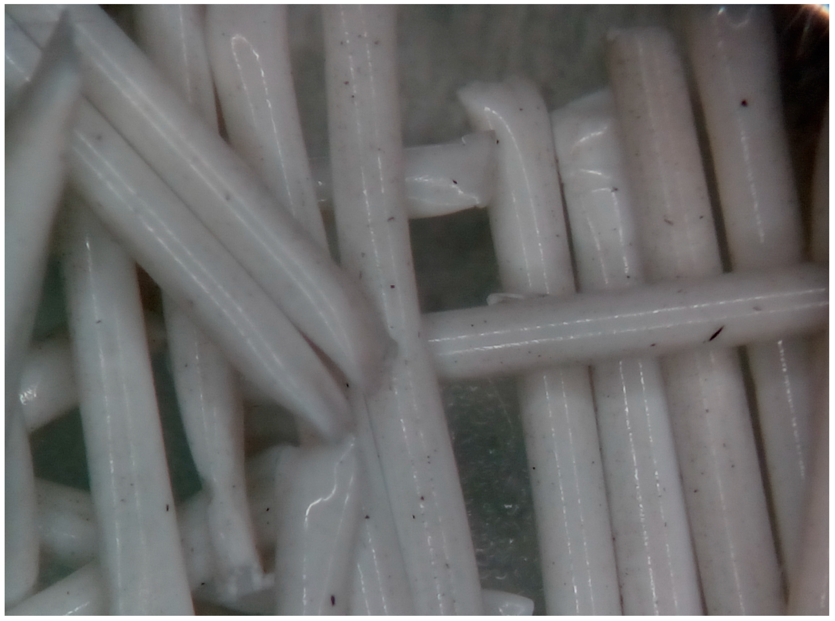
Ultrafilters from two centers showing signs of contamination were received in the IIS-FJD Renal research laboratory within a one-year period. Macroscopically, they were similar. At 20× magnification, the presence of soot-like particles was observed on the fiber surface in both of the samples (Figure 2).
3.1. Analysis of Ultrafilter Soot-Like Particles from Dialysis Center 1
In the microscopic analysis, soot-like black particles were observed. Ultramicroscopic analysis using SEM showed scale deposition in more than 50% of the surface of the membrane (Figure 3A,C). A general (Figure 3B) and focused (Figure 3D) elemental chemical analysis showed a similar composition, which is rich in silica in combination with oxygen, magnesium, sodium, or chlorine, as consistent with the presence of silicates.
3.2. Analysis of Ultrafilter Soot-Like Particles from Dialysis Center 2
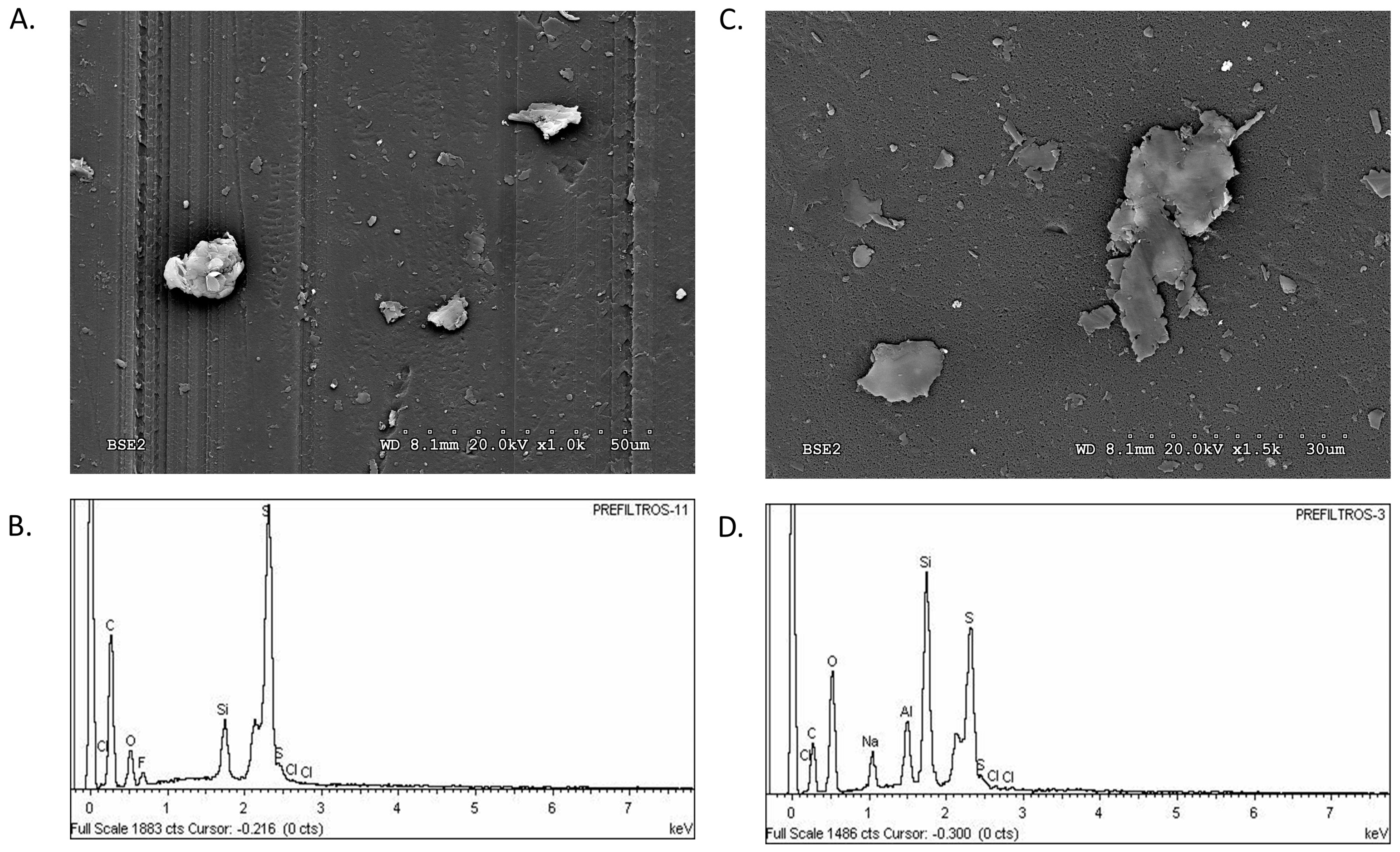
The microscopic analysis of the soot-like particles in ultrafilters from DC2 disclosed particles that were identical to those in DC1 ultrafilters, although the amount was lower. Analysis of relatively large areas disclosed the presence of carbon, oxygen, and sulfur, as consistent with components of the dialyzer membrane polymer (polyethersulfone). Additionally, this analysis disclosed traces of silica, whose signal increases as the analysis focused on specific particles. As in the previous case, the presence of silica was associated with an increased signal for oxygen, aluminum, and alkaline metals (Figure 4).
3.3. Morphological and Chemical Analysis of the Ion-Exchange Resin and Activated Carbon Filters Employed in Dialysis Water Treatment
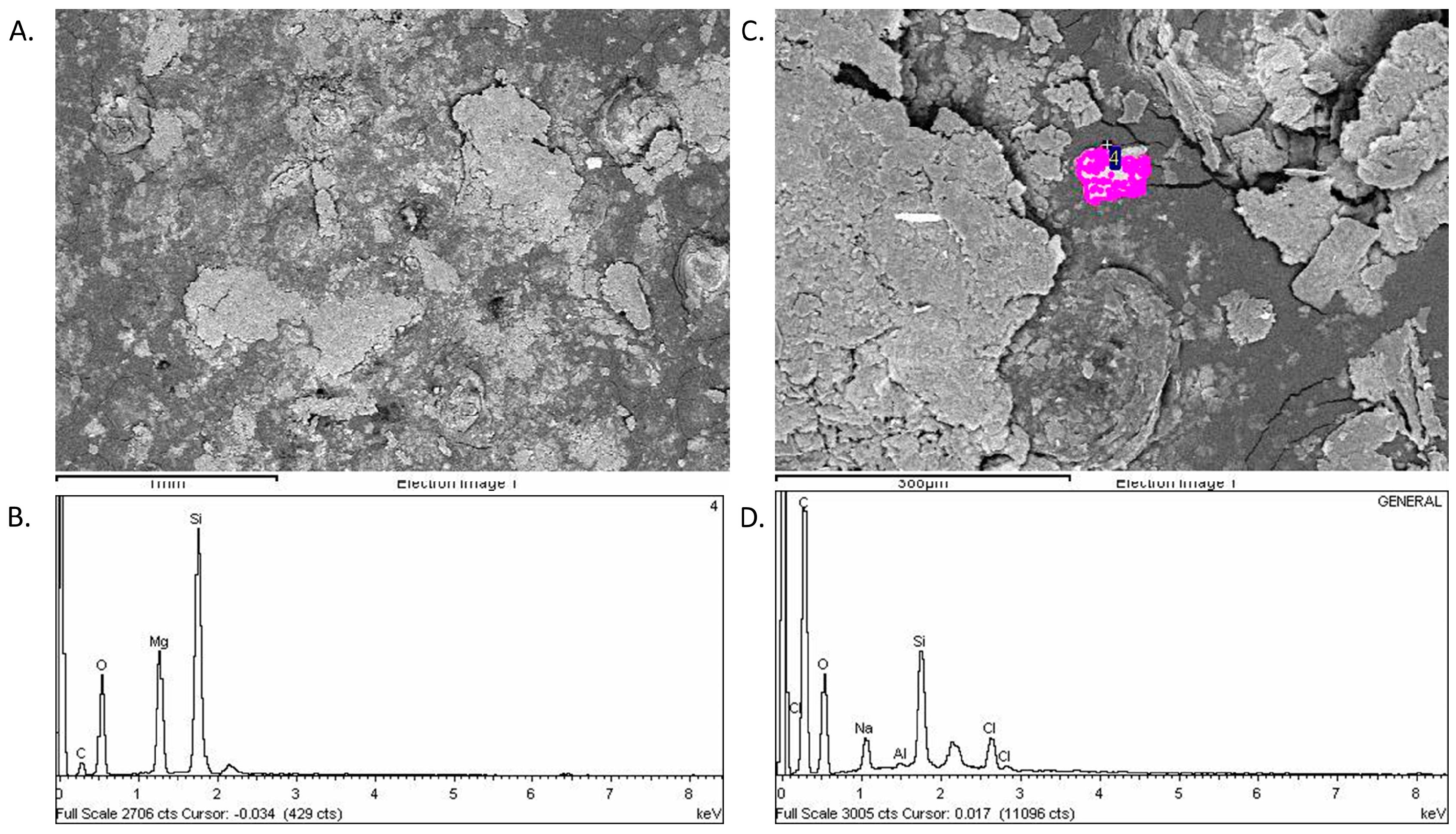
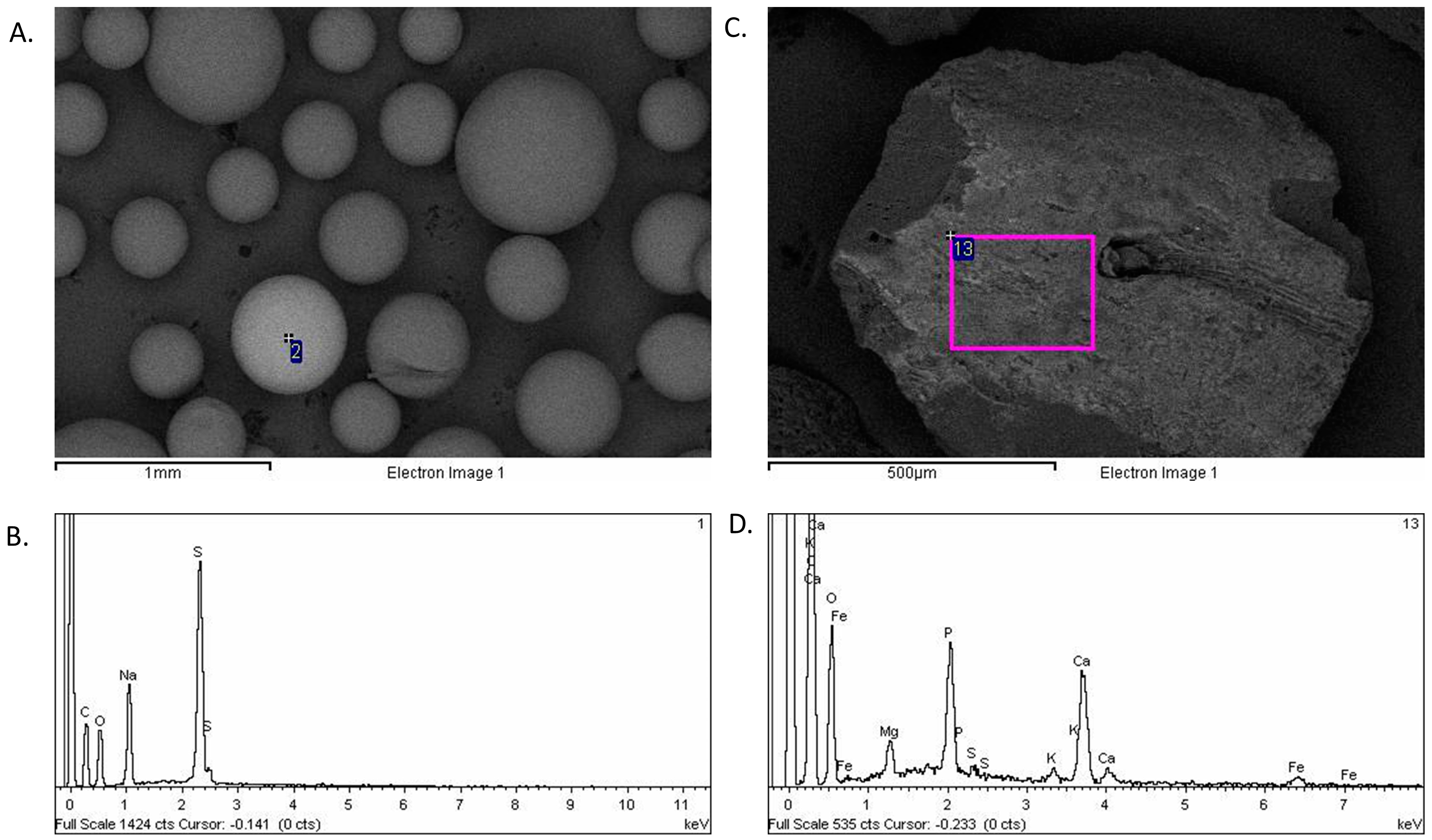
The ion-exchange resin and activated carbon filters were analyzed to assess the possibility of leakage of carbon filters and resins into the water treatment circuit. Figure 5 shows the electron microscopy image of resin filter particles (Figure 5A) and their chemical composition (Figure 5B). In the composition analysis, no signal is observed for aluminum or silica, which were characteristic of the soot-like contaminating particles.
Similarly, Figure 5C shows an electronic micrograph of one of the activated carbon particles from the water purification system. The elemental analysis revealed the presence of many components other than carbon, such as phosphorus, calcium, magnesium, and even iron ions. But, as in the previous case, both aluminum and silica were absent. This suggests that neither the resin nor the activated carbon in the water purification system are the origin (at least in appreciable quantities) for the contaminating particles that were identified in the ultrafilters.
3.4. Comparative Analysis
The composition of materials in ultrafilters from both of the dialysis units was very similar. The electron microscope appearance and the elemental chemical composition differed from the carbon and resin particles that were used in water treatment systems.
Enrichment in silica suggests that particulate material was formed by silicates that were contained in clay. Leakage of these particles to the circuit appeared to be the cause of ultrafilter contamination in both centers. The most likely explanation was a fortuitous passage of untreated water to the dialysis unit circuit. Both of the events occurred in island hospitals, where much of the water supply comes from underground aquifers, which may explain the presence of traces of clay, especially during summer months or drought times when water levels run low. Unfortunately, no contemporary water samples from the same aquifers was available for analysis. Ultrafilters prevented this material from ending up in the dialyzers with the risk that it might entail.
4. Discussion
Given the high comorbidity in hemodialysis patients and the complexity of the dialysis treatment, it is remarkable how rarely a life-threatening complication occurs during dialysis. The low rate of major complications can be attributed to numerous safety features in modern dialysis machines; meticulous treatment and testing of dialysate fluids to prevent exposure to trace elements, toxins, and pathogens; adherence to detailed treatment protocols; and, extensive training of dialysis staff to handle medical emergencies. Most hemodialysis emergencies can be attributed to human error [11]. Patients on hemodialysis are exposed to around 120 L dialysate water (e.g., dialysate flow 500 mL/min for 240 min) during an average dialysis session [12]. With the dialysis membrane being the only barrier between the dialysate and blood, it is critical that water undergoes rigorous purification before its use during dialysis [4,5,6,7].
The most frequent complications resulting from hemodialysis dialysate are pyrogenic reactions during a dialysis session due to multiple causes, including water/dialysate bacterial or endotoxin contamination [13,14]. In this regard, dialysis unit protocols include water system maintenance, disinfection, and periodic checks and evaluation by water cultures and endotoxin assays.
Dialysis water pre-treatment consists of removing most of the particles in suspension. This step is usually achieved by several filters (Figure 1), which must be checked and changed periodically and their duration is conditioned by the number of particles of the water supply [3]. Pretreated water then passes through reverse osmosis columns that should prevent particles from reaching the dialysis monitor, unless the membranes are broken. Sterile ultrafilters are used to prepare the substitution fluid that is given to patients undergoing dialysis with high convective fluid removal and replacement. Retention of pyrogenic agents by the ultrafilters is crucial in avoiding inflammatory responses. These ultrafilters were designed to keep ultrapure dialysis fluid free from bacterial endotoxins and other microbial contamination [15]. We now present another important function of the ultrafilters: preventing exposure to trace elements and other particles that may result from human error or system dysfunction.
The initial hypothesis was that the soot-like particles represented contamination by coal particles from activated charcoal filters that had reached the monitor. However, this was unlikely since no defect in reverse osmosis columns was observed in any of the two centers. The composition of the material that was found in both of the ultrafilters is consistent with clay. Clay, which is a major component of sludge, is common in waters of general use in places where there are no underground currents or rivers. Both cases originated in islands. Tap water in certain islands is characterized by its hardness (lime content) with salt and sludge residues, due to the fact that the water supply is not homogeneous: central water is usually is a mix of small reservoirs, deep wells, and water from desalination plants (reverse osmosis). During summer months or after draughts, the concentration of such clay may be increased.
It is yet unclear how the material reached the ultrafilters in the hemodialysis machine. The only plausible explanation is that general use water was allowed fortuitously directly into the dialysis monitor, since contamination of the exchange resin and carbon filters was ruled out. In both cases, the problem was transient, and the ultrafilters prevented the particles from reaching the dialyzer, and thus, to contact the patient blood. Analysis of the particles allowed for a correct diagnosis of the system dysfunction and a correct application of measures to prevent further episodes of contamination. This is key to preserve patient safety. In this regard, the methods that are described here may be used for the analysis of future contaminants of water treatment and dialysis systems. To minimize the probability of such situations in the future, a correct training and periodical re-retraining of staff is mandatory and should encompass water treatment system maintenance. Especially in summer months, extreme care should be taken with system maintenance. Visual inspection of circuits and replaced items will help in identifying safety issues and a detailed physic-chemical analysis of any abnormal material may help to pinpoint the source of contamination.
5. Conclusions
Ultrafilter contamination should be analyzed as it draws attention to potential risks to patient safety. Physical analysis allowed for quickly identifying the accumulated macroscopic material. In conclusion, physical analysis of macroscopic ultrafilter abnormalities may help to pinpoint the source of malfunction and to provide corrective action.
Acknowledgments
The studies described above have been funded by the Spanish Ministry of Economy and Competitiveness and European Regional Development Founds (ERDF/FEDER) through ISCIII/FIS grants PI16/01298, PI17/01495, CIBERDEM and REDINREN RD016/0019 and through Madrid Renal Society (SOMANE) grants. The authors thank the “Servicio Interdepartamental de Investigación” (Sidi) of the Universidad Autonoma de Madrid (UAM), and in particular Enrique Rodriguez.
Author Contributions
S.M. and E.G.P. conceived and designed the experiments; S.M. analyzed the data; A.O.; J.E, E.G.P. and S.M. wrote the paper.
Conflicts of Interest
The authors declare no conflict of interest.
References
- United States Renal Data System (USRDS). USRDS Annual Data Report Volume 2: ESRD in the United States; National Institute of Diabetes and Digestive and Kidney Diseases (NIDDK): Bethesda, MD, USA, 2015.
- Sheth, R.A.; Sheth, A.U. A Primer on Hemodialysis From an Interventional Radiology Perspective. Tech. Vasc. Interv. Radiol. 2017, 20, 9–13. [Google Scholar] [CrossRef] [PubMed]
- Pérez-García, R.; García Maset, R.; Gonzalez Parra, E.; Solozábal Campos, C.; Ramírez Chamond, R.; Martín-Rabadán, P.; Sobrino Pérez, P.E.; Gallego Pereira, O.; Dominguez, J.; de la Cueva Matute, E.; et al. Comisión de Expertos de la Sociedad Española de Nefrología para la creación de la Segunda Edición de la Guía de Gestión de Calidad del Líquido de Diálisis Guideline for dialysate quality of Spanish Society of Nephrology (second edition, 2015). Nefrologia 2016, 36, e1–e52. [Google Scholar] [CrossRef] [PubMed]
- Kasparek, T.; Rodriguez, O.E. What Medical Directors Need to Know about Dialysis Facility Water Management. Clin. J. Am. Soc. Nephrol. 2015, 10, 1061–1071. [Google Scholar] [CrossRef] [PubMed]
- Layman-Amato, R.; Curtis, J.; Payne, G.M. Water treatment for hemodialysis: An update. Nephrol. Nurs. J. 2013, 40, 383–404. [Google Scholar] [PubMed]
- Fendley, D.A.; Ward, R.A. Dialysate quality: New standards require a new approach to compliance. Semin. Dial. 2012, 25, 510–515. [Google Scholar] [CrossRef] [PubMed]
- Penne, E.L.; Visser, L.; van den Dorpel, M.A.; van der Weerd, N.C.; Mazairac, A.H.A.; van Jaarsveld, B.C.; Koopman, M.G.; Vos, P.; Feith, G.W.; Kremer Hovinga, T.K.; et al. Microbiological quality and quality control of purified water and ultrapure dialysis fluids for online hemodiafiltration in routine clinical practice. Kidney Int. 2009, 76, 665–672. [Google Scholar] [CrossRef] [PubMed]
- European Best Practice Guidelines Expert Group on Hemodialysis, E.R.A. Section IV. Dialysis fluid purity. Nephrol. Dial. Transplant 2002, 17 (Suppl. 7), 45–62. [Google Scholar]
- Davenport, A. New Dialysis Technology and Biocompatible Materials. In Contributions to Nephrology; Karger Publishers: Basel, Switzerland, 2017; Volume 189, pp. 130–136. [Google Scholar]
- Lee, K.; Pino, C.J.; Humes, H.D. Substitution-free hemodiafiltration. ASAIO J. 2012, 58, 514–521. [Google Scholar] [CrossRef] [PubMed]
- Saha, M.; Allon, M. Diagnosis, Treatment, and Prevention of Hemodialysis Emergencies. Clin. J. Am. Soc. Nephrol. 2017, 12, 357–369. [Google Scholar] [CrossRef] [PubMed]
- Perez-Gomez, M.V.; Gonzalez-Parra, E.; Ortiz, A. Haemodialysate: Long neglected, difficult to optimize, may modify hard outcomes. Clin. Kidney J. 2015, 8, 576–579. [Google Scholar] [CrossRef] [PubMed]
- Ward, R.A. Water processing for hemodialysis. Part I: A historical perspective. Semin. Dial. 2008, 10, 26–31. [Google Scholar] [CrossRef] [PubMed]
- Ledebo, I. Purification of dialysis fluid: Historical background and perspective. Blood Purif. 2009, 27 (Suppl. 1), 17–19. [Google Scholar] [CrossRef] [PubMed]
- Ledebo, I. Ultrapure dialysis fluid—Direct and indirect benefits in dialysis therapy. Blood Purif. 2004, 22 (Suppl. 2), 20–25. [Google Scholar] [CrossRef] [PubMed]
Figure 1.
Water treatment diagram. Pretreatment should achieve the highest possible elimination of particles, the disappearance of chloramines and other organic matter and a decrease of the number of cations. The first element is a sand and anthracite filter, followed by additional filters, a double descaler by exchange resins; and two activated carbon filters. Carbon filters eliminate chloramine and chlorine from dialysate. Pretreated water then passes through reverse osmosis columns. Ultrafilters are highlighted in red, where contamination was found in the present report. Ultrafilters are the last safety feature before dialysate infusion and prevent compounds leaked from previous steps to reach the dialyzer.

Figure 2.
Optical microscopy view of ultrafilter fibers extracted from their case (Original magnification 20×).
Figure 2.
Optical microscopy view of ultrafilter fibers extracted from their case (Original magnification 20×).

Figure 3.
Electron microscopy images of particles found on ultrafilters from dialysis center 1. (A) General view of deposits on the membrane. (B) Elemental chemical composition. (C) Magnification of deposit scales on the membrane. (D) Elemental chemical composition of contaminant shown in (C).
Figure 3.
Electron microscopy images of particles found on ultrafilters from dialysis center 1. (A) General view of deposits on the membrane. (B) Elemental chemical composition. (C) Magnification of deposit scales on the membrane. (D) Elemental chemical composition of contaminant shown in (C).

Figure 4.
Electron microscopy images ultrafilter fibers from Dialysis center 2. (A) 1000× magnification showing flake-like particles. (B) Elemental composition of the particles in (A). (C) 1500× magnification of another particle and (D) Composition of the purple particle in (C). Particles in (B–D) have a higher signal for Si, O, Al, Na, and K.

Figure 5.
Electron microscopy images of water purification components. (A) Image and (B) composition of the ion exchange resin. (C) Image and (D) composition of activated carbon.
Figure 5.
Electron microscopy images of water purification components. (A) Image and (B) composition of the ion exchange resin. (C) Image and (D) composition of activated carbon.


Table 1.
Main water pollutants classified into particles and solutes.
| Particles | Minerals | – |
|---|---|---|
| Colloids | – | |
| Solutes | Inorganics ions | Cations (Na, Ca, Mg, Fe, Zn, Cu, Pb, and others) |
| Anions (Cl, F, NO3, SO4, HCO3) | ||
| Organics | Natural substances (Lignin, tannins and others) | |
| Non-natural substances (Chemical pollutants) | ||
| Endotoxins from microorganisms | ||
| Microorganisms | Bacteria, Yeasts, Fungi, Protozoa, Viruses | |
| Other added chemicals | Antimicrobials or algaecides (chlorine, fluorine, chloramine), flocculating agents (Al2(SO4)3·14H2O) and others |
© 2018 by the authors. Licensee MDPI, Basel, Switzerland. This article is an open access article distributed under the terms and conditions of the Creative Commons Attribution (CC BY) license (http://creativecommons.org/licenses/by/4.0/).
Share and Cite
MDPI and ACS Style
Mas, S.; Egido, J.; Ortiz, A.; Gonzalez-Parra, E. Identification and Chemical Characterization of Insoluble Contaminants in Hemodialysis Water Treatment. Water 2018, 10, 486. https://doi.org/10.3390/w10040486
AMA Style
Mas S, Egido J, Ortiz A, Gonzalez-Parra E. Identification and Chemical Characterization of Insoluble Contaminants in Hemodialysis Water Treatment. Water. 2018; 10(4):486. https://doi.org/10.3390/w10040486
Chicago/Turabian StyleMas, Sebastian, Jesús Egido, Alberto Ortiz, and Emilio Gonzalez-Parra. 2018. "Identification and Chemical Characterization of Insoluble Contaminants in Hemodialysis Water Treatment" Water 10, no. 4: 486. https://doi.org/10.3390/w10040486
Note that from the first issue of 2016, this journal uses article numbers instead of page numbers. See further details here.