Hydraulic Jumps in Adverse-Slope Stilling Basins for Stepped Spillways
by
 , ,
, ,
Robert Ljubičić
1,* ,
,
Budo Zindović
1 ,
,
Predrag Vojt
2,
Dragutin Pavlović
1,
Radomir Kapor
1 and
Ljubodrag Savić
1 1
Faculty of Civil Engineering, Department of Hydraulic and Environmental Engineering, University of Belgrade, 11000 Belgrade, Serbia
2
Institute for the Development of Water Resources “Jaroslav Černi”, Jaroslava Černog 80, 11226 Belgrade, Serbia
*
Author to whom correspondence should be addressed.
Water 2018, 10(4), 460; https://doi.org/10.3390/w10040460
Submission received: 15 March 2018
/
Revised: 4 April 2018
/
Accepted: 9 April 2018
/
Published: 11 April 2018
(This article belongs to the Section Hydraulics and Hydrodynamics)
Abstract
:The performance of flat stilling basins can be inadequate for conditions when the tailwater depth is insufficient for hydraulic jump stabilization. In such cases, adverse-slope stilling basins can be used because they reduce the necessary tailwater depth. Sloped basins combined with smooth chutes have been the subject of many studies. However, limited research has been done for basins with stepped chutes, which are characterized by intensive flow aeration and high energy dissipation. Based on our scale-model experimental measurements of depth, velocity, and air concentration, we present a momentum-based method to characterize such hydraulic jump: the sequent depth ratio, the length of hydraulic jump roller, and energy dissipation effectiveness. The proposed method provides better agreement with experimental data when compared to existing methods and can be used for preliminary design.
1. Introduction
Hydraulic jump stilling basins are the most commonly used energy dissipators. However, the roller of the hydraulic jump must be inside the basin, preventing potential downstream erosion.
Stepped spillways have attracted the interest of engineers and researchers over the last few decades, following the development of roller-compacted concrete (RCC) dams. This type of spillway offers better dissipation capabilities than smooth chutes, significantly reducing the size and cost of stilling basins. Stepped spillways have been thoroughly investigated by Boes and Hager [1,2], who offered a method for estimating the depths of the air-water mixture, air-concentrations, and energy dissipation effectiveness for skimming flow regime. This paper continues along the same line by considering skimming flow only.
Hydraulic jumps on sloping channels with flat stilling basins were first classified by Kindsvater [3]. According to this classification, a B type jump begins in the upstream channel of a positive slope and ends in the flat downstream channel. Bradley and Peterka [4] conducted experiments involving B jumps for a wide range of incoming Froude numbers (2 < F < 18). Rajaratnam [5,6] stated that the dissipation efficiency of the B jump depends on the incoming Froude number and the spillway slope. Hager [7] investigated B jumps on a 45° chute and obtained an equation for estimating the characteristics of such hydraulic jumps. He stated that the effectiveness of the B jump is lower than that of an A type or classical hydraulic jump on the flat bed. Kawagoshi and Hager [8] extended Hager’s earlier research to 30° spillways, while also analyzing the velocity field in the occurring hydraulic jump. Ohtsu and Yasuda [9] derived an expression for the estimation of sequent depth ratio for B jumps, based on experiments on 23° to 55° spillway bed angles. Adam et al. [10] presented their own expressions for estimating the characteristics of B jumps for 11.3°, 14.0°, and 18.4° chutes, and incoming Froude numbers ranging from 2.4 to 7.4. Carollo, Ferro, and Pampalone [11] performed a dimensional analysis and derived empirical expressions for B jumps, based on measurements for 8.5°, 17.5°, and 30° spillway angles. Recently, Bejestan, and Shokrian [12] analyzed the behavior of B jumps on rough surface beds, while Montano and Felder [13] investigated air-water mixture properties for B jumps.
Less research has been done for sloped stilling basins. According to classification by [5], F jumps form entirely on adversely sloped aprons. Rouse [14] stated that hydraulic jumps on adversely sloped aprons are inherently unstable and difficult to control. Defina, Susin, and Viero [15] investigated the impact of bed friction on the stability of the F jump. They stated that the F jump can be successfully stabilized for small adverse slopes of the apron. A general conclusion is that whenever the weight of the water in the hydraulic jump is acting opposite to the flow, it exhibits unstable behavior similar to undular hydraulic jumps. Empirical expressions for F jumps were proposed by [3,16,17]. More recently, Beirami and Chamani [18,19] suggested a new type, called the B-F jump, which begins in the upstream channel of positive slope (spillway) and ends in the downstream channel of adverse (negative) slope. They stated that the B-F jump exhibits stable behavior and presented a momentum-based method for estimating the sequent depth ratio, the hydraulic jump length, and the energy dissipation efficiency for both F and B-F jumps. Bateni and Yazdandoost [20] presented a similar semi-empirical method, based on the momentum analysis of the hydraulic jump and their experimental results.
To this date, limited research was published on the combined effects of stepped chute spillways and adverse-slope stilling basins. Stepped spillways display significantly different behavior than smooth chutes of ogee spillways (intensive aeration of the flow, significant energy dissipation and irregular velocity distribution in the flow). It is, therefore, of practical interest to examine how they perform in combination with adverse-slope basins. In this paper, we used a momentum analysis and experimental data to derive a method for estimating the characteristics of such hydraulic jumps. In addition, we discussed the feasibility of using adverse-slope hydraulic jump configurations when the tailwater depth is insufficient for hydraulic jump stabilization.
2. Methods and Materials
In this section, we presented a method for estimating the essential characteristics of hydraulic jumps on adverse-slope aprons for stepped spillways. First, the theoretical relations for F and B-F jumps were proposed. Then the results of the scale model investigation were presented, which were used to verify and calibrate the theoretical relations. In addition to F and B-F jumps, the applicability of the proposed method was tested and verified for B jumps as well.
2.1. F and B-F Type Jump
According to the notation in Figure 1, we examined three positions of the hydraulic jump with different lengths L1: (1) L1 = 4.5 cm (beginning of the hydraulic jump close to the spillway toe, classified as F jumps); (2) L1 = 9.0 cm (B-F jumps); and (3) L1 = 13.5 cm (B-F jumps). Hydraulic jumps were established with stable behavior in all three positions. The momentum-based approach was used to determine the essential characteristics of the hydraulic jump: the sequent depth, h2 (assumed to be equal to the clear-water depth due to the lack of significant aeration in Section 2, i.e., h2 = hw2), the roller length, Lr, and the energy dissipation coefficient, η.
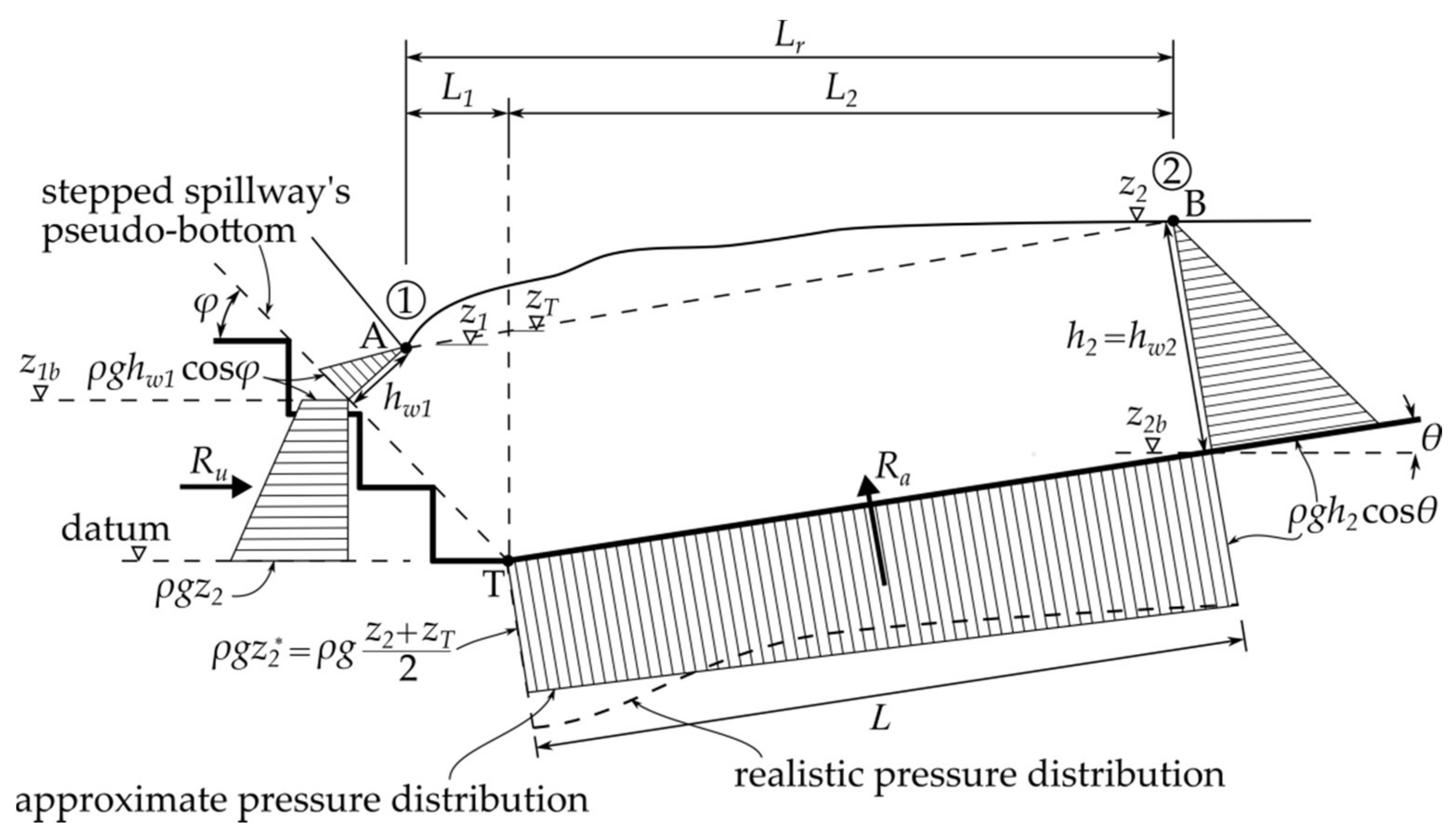
By applying the momentum conservation law in the horizontal direction (Figure 1), we obtained:
where Ra is the apron reaction force, Ru is the bed pressure component for the stepped spillway bottom, hw1 and h2 are clear-water depths in Section 1 and Section 2 that are measured perpendicular to the streamlines in Section 1 and Section 2, v1 and v2 are the corresponding depth-averaged velocities, q is the unit discharge, g is the gravitational acceleration, ρ is the clear-water density, and β is the momentum correction factor. Similar to [18,20], the bed shear force was neglected in Equation (1).
Bateni and Yazdandoost [20] introduced a linear expression for pressure head at the spillway toe (point T in Figure 1). This can lead to erroneous results as this value is unbounded. To alleviate this issue, we introduced a bounded approximation of the pressure head for calculating the reaction force Ru, z2* = (zT + z2)/2, where zT corresponds to the water level above point T that falls on the segment AB (Figure 1). Parameter z2* is introduced to account for the centrifugal force at the toe of the chute and the resulting local increase of pressure. This contrasts with [18], who included the radius of the curved chute-stilling basin transition. Since such transition is generally omitted for stepped chutes, to compare our results with their method, the equivalent radius was later estimated by data fitting.
Using notation from Figure 1, Equation (1) was rewritten as:
where z1b is the pseudo-bottom elevation at Section 1, z2 is the water level at Section 2, and L is the streamwise distance from point T to the end of the hydraulic jump roller at Section 2, which can be obtained as L = (Lr – L1)/cos θ + h2 tan θ. Equation (2) can be written in a simplified form:
where D = h2/hw1, C = cos θ/cos φ, D1 = z1b/(hw1 cos φ), D2 = z2/(hw1 cos φ), DL = L/(hw1 cos φ), D2* = z2*/(hw1 cos φ), and F1 = v1/(g hw1 cos φ)0.5 is the inflow Froude number [7].
Determining the characteristics of the incoming flow, the clear-water depth, hw1, and the mean velocity, v1, can be challenging for stepped chute spillways. Carollo, Ferro, and Pampalone [11] stated that the accuracy of each method for estimating the characteristics of the B-F and F jumps is highly dependent on the accurate estimation of the incoming flow characteristics (i.e., clear-water depth hw1). We compared two methods for estimating hw1:
- Integrating the measured air concentration profiles:where h90 is the mixture depth at which the air concentration, Ca, equals 0.9.
The idea behind the comparison is to evaluate the accuracy of the Boes and Hager method for estimating the incoming depth and velocity for the F and B-F type jumps. If proven adequate, these values can be used instead of the measured data for stepped spillway, where spillway depth and velocity measurements are challenging.
The length L must be estimated prior to solving Equation (3). The two types of expressions for relative lengths of the hydraulic jump roller, Lr/hw1 and Lr/h2, were considered:
The exact forms of the expressions (5) were estimated from experimental data. Based on the Equations (3) and (5), the observed and predicted sequent depth ratios, D, and sequent depths, h2, were calculated.
The energy dissipation coefficient of a hydraulic jump, η, was defined as [7]:
where E1 and E2 are the energy heads in Section 1 and Section 2. To determine the effects of different apron angles θ and hydraulic jump positions L1, a comparison with the classical hydraulic jump configuration was performed by using the Bélanger equation [21]:
where hB is the downstream sequent depth for the classical hydraulic jump.
2.2. B Type Jump
To verify the applicability of the method developed for B-F and F jumps, the equations were tested with B jumps as well. Since a B jump occurs only in flat stilling basins, the momentum equation given by Equation (3) is simplified as follows:
where C′ = 1/(cos φ). For B jumps, either Equation (3) or Equation (8) can be used, as they are equivalent for θ = 0°.
We assumed that the same equations for the roller length and the energy dissipation coefficient (Equations (5) and (6)) can be applied to B jumps as well.
2.3. Scale Model
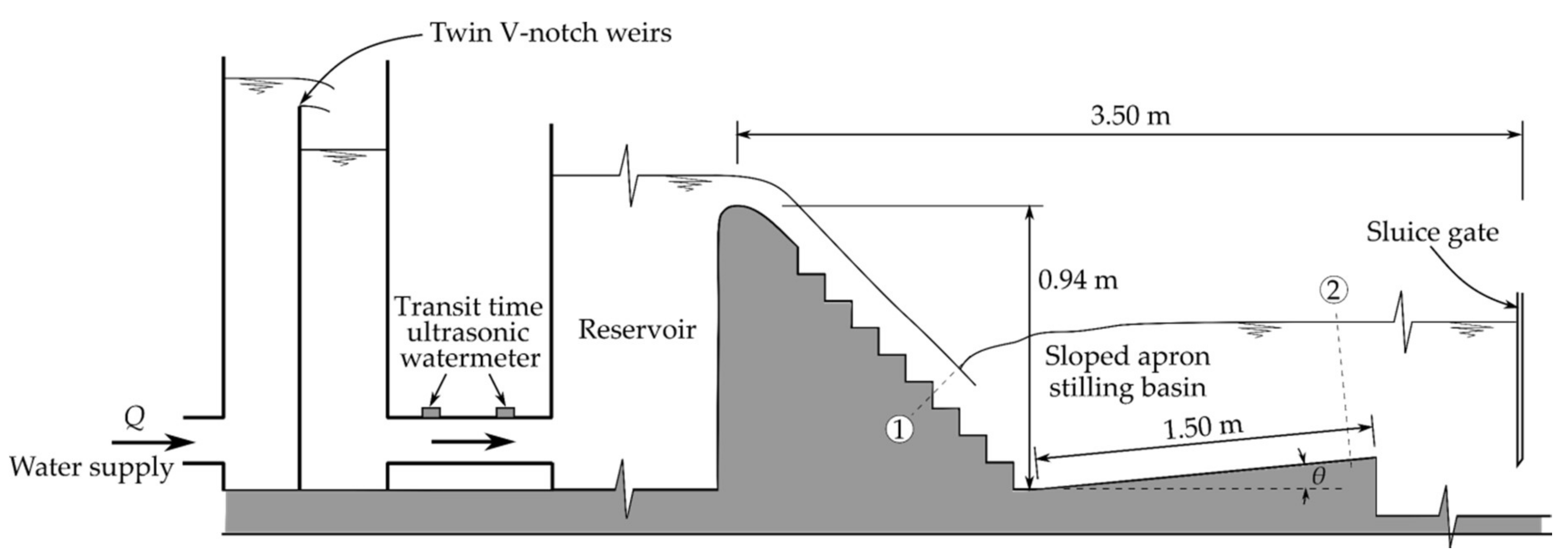
The experiments were performed in the Hydraulic laboratory of the Civil Engineering Faculty at the University of Belgrade. A scale model of the stepped spillway (Figure 2), 0.94 m high (from the weir crest to the spillway toe), and 0.46 m wide, was constructed. The angle of the chute pseudo-bottom was φ = 45°. The chute consisted of 17 steps with the height of each step being s = 0.045 m. Downstream of the spillway, a 1.5 m long hinged sloped apron was constructed. Four angles of the apron were examined, θ = {0°, 2.5°, 5°, 7.5°}. The tailwater level was controlled by a sluice gate. The total length of the flume, from the weir crest to the gate was 3.5 m.
The discharge rates varied from Q = 16 L/s to Q = 52.5 L/s. For discharges smaller than approximately 16 L/s, the skimming flow regime suggested by [22] could not be attained. Due to the limitations of the model, discharges larger than 52.5 L/s could not be achieved. Hence, the incoming Froude numbers were in the range of 7.3 > F > 9.6, which is the range of the most practical significance [16].
2.4. Scale Model
Most studies about B, F, and B-F jumps used the incoming depth measured with a point gauge. Measuring the water level in stepped chutes presents a serious challenge, due to the intensity of the turbulence and air entrainment. To determine the incoming depths, h1 and hw1, and depth-averaged velocity, v1, we used the method proposed by [1,2]. To verify these results, we measured h1 and v1 with a multi-tip electro-conductivity (EC) probe, similar to [23,24,25]. The probe was equipped with 4 tips (4 channels). Data were sampled at 19.2 kHz per channel for 100 seconds to obtain stable averages. The uncertainty of the air concentration measurement was estimated to ±3%.
The length of the roller, Lr, was found using light tracer particles scattered on the water surface and verified for each case by observing the air bubble pattern, similar to [20]. The location of the end of the roller was marked as Section 2 (Figure 1 and Figure 2), and it was found as the stagnation point for the tracer particles (i.e., particles do not move either downstream nor upstream). The uncertainty of the roller length measurement was estimated to ±1 cm.
The depth at the end of the roller (Section 2) was determined with a gauge. The uncertainty of the depth measurements was ±0.5 cm due to fluctuations of the water level.
The discharge, Q, was measured using twin sharp-crested V notch weirs and verified using a transit-time ultrasonic flowmeter, located on the supply line of the reservoir (Figure 2). The uncertainty of the flow-rate measurements was estimated to 2%.
3. Results and Discussion
In the following section, results are grouped according to the characteristics of F, B-F, and B jumps: (1) roller length, (2) sequent depth ratio, and (3) energy dissipation efficiency. A summary of the results is given in Table 1 and Table 2 at the end of this article.
3.1. Roller Length
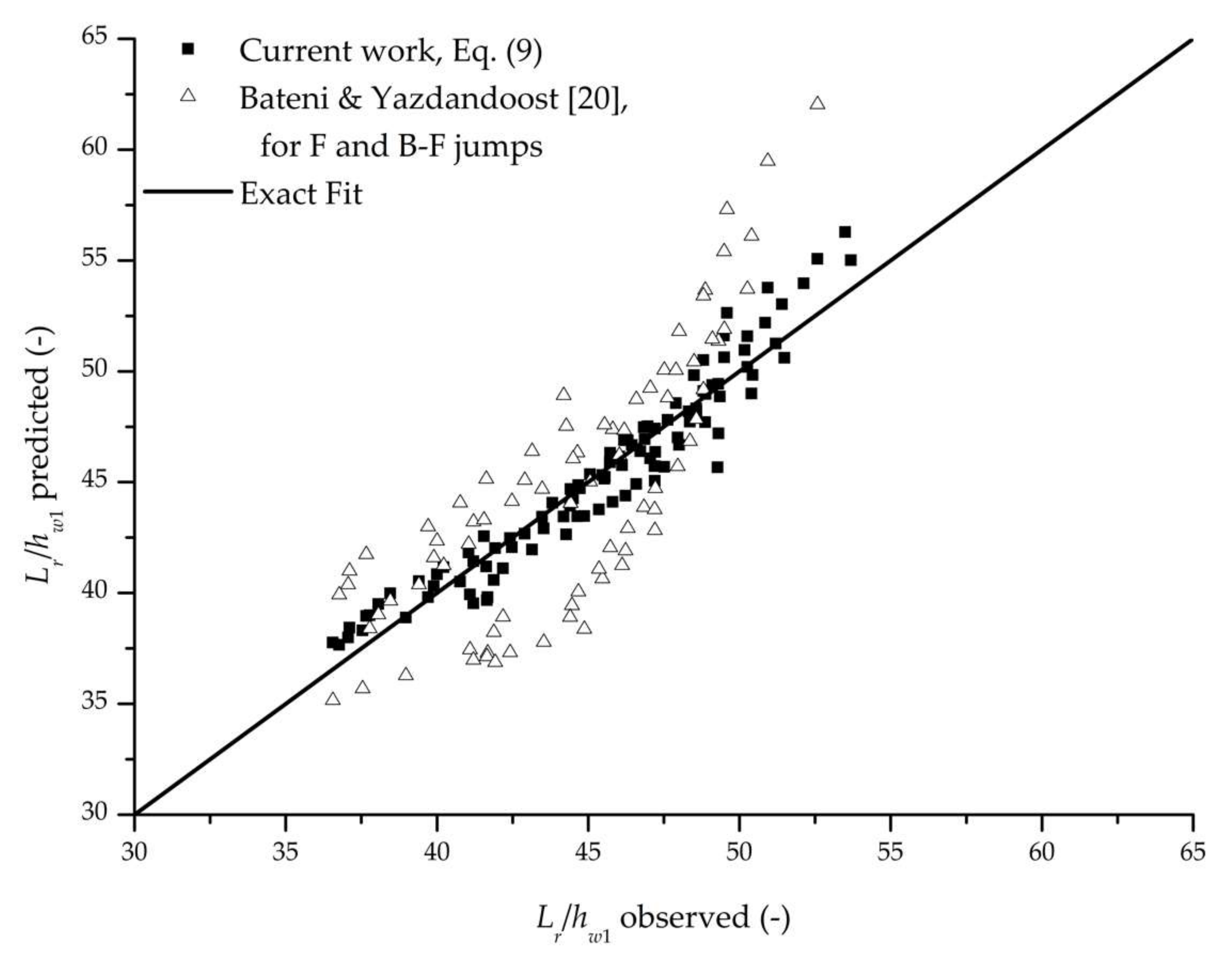
Estimating the main characteristics of B, F, or B-F jumps through the momentum conservation law requires two separate equations—one for the roller length, Lr, and one for sequent depth ratio, D. Based on the assumed functions in Equation (5), the measured hydraulic jump lengths were fitted to an empirical curve (R2 = 0.932 for the entire dataset):
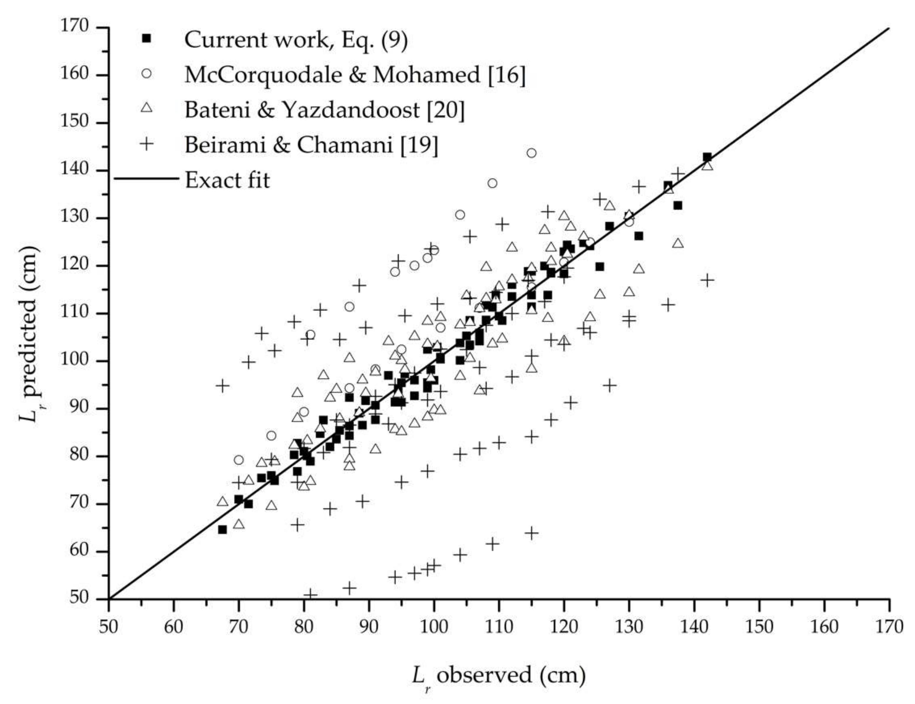
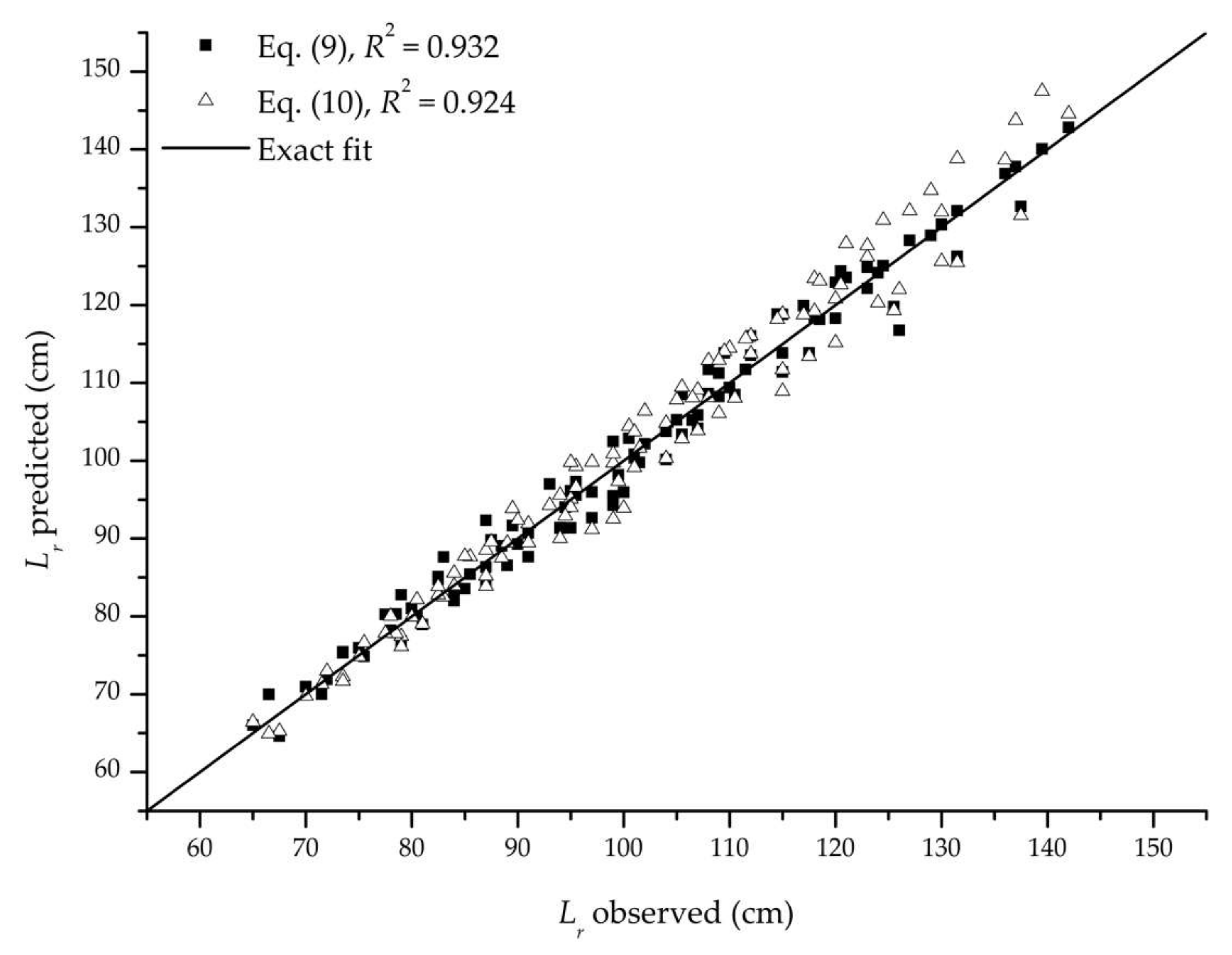
where a = 0.2131(tan θ)−0.15 for F and B-F jumps, and a = 0.358 for B jumps. Observed and predicted values for relative roller lengths, Lr/hw1, and roller lengths, Lr, based on Equation (9) are presented in Figure 3, Figure 4 and Figure 5. The methods of [16,20] were also applied to experimental data, and are presented in Figure 4. A linear regression was found for Lr/h2 relation (R2 = 0.924 for the entire dataset):
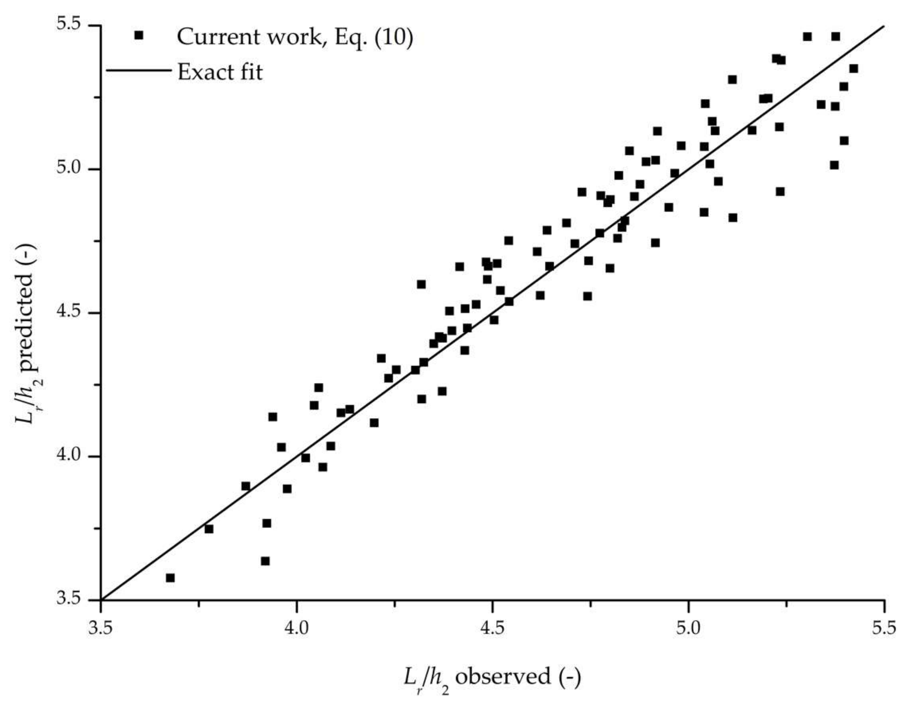
and the observed and the predicted values for Lr/h2 and Lr based on the Equation (10) are presented in Figure 5 and Figure 6. Along with R2 values, normalized root mean square errors (NRMSEs) have also been determined as:
where Xobs and Xpred are observed and predicted valued of the hydraulic jump characteristics, and N is the total number of tests (N = 104). The NRMSE of Equation (9) was determined to be 6.63%, while Equation (10) had 6.47%. This shows that both proposed empirical expressions (Equations (9) and (10)) agree well with the experimental results (Figure 3, Figure 4, Figure 5 and Figure 6). However, the use of the Equation (9) is preferred since it does not require the estimation of the depth h2. Thus, the use of Equation (9) should reduce the total uncertainty of the method. This was easily shown by the NRMSE values for the estimation of the Lr. Normalized RMSE of the Equation (9) was 3.15%, and of the Equation (10) was 4.51%.
The results in Figure 4 show that the method of [20] yields good results, but with larger and approximately symmetrical scatter, ranging between −15% and +18% relative to measured data. This can be attributed to a wider range of the incoming Froude numbers achievable on classical smooth chutes, and the lack of air entrainment in their experimental setup. On the other hand, results obtained with the method of [16] fail to account for the different apron slopes. Results obtained by method [19] adequately follow the trend of measured values. However, they are very scattered, with relative errors between −17% and +34%. Results obtained by [19] fail to account for different positions of the hydraulic jump. We hypothesize for methods [16,19] that the observed disagreements exist due to differences in experimental setups, the sensitivity of their equations, and their coefficients being problem dependent.
3.2. Sequent Depth
Table 3 shows that the incoming clear-water depth, hw1, is underestimated by −1 to −5% with the method by [1,2] when compared to EC probe measurements. This indicates that their method can be used to estimate the incoming flow depth, hw1, and velocity, v1, and it was adopted in this paper.
Based on the measured velocity distribution in the incoming flow (Figure 7), the average value of β1 = 1.186 was used in Equations (3) and (8). For Section 2, the velocity measurement with an EC probe was not possible due to the lack of significant air concentration, and consequently, β2 was assumed to be unity.
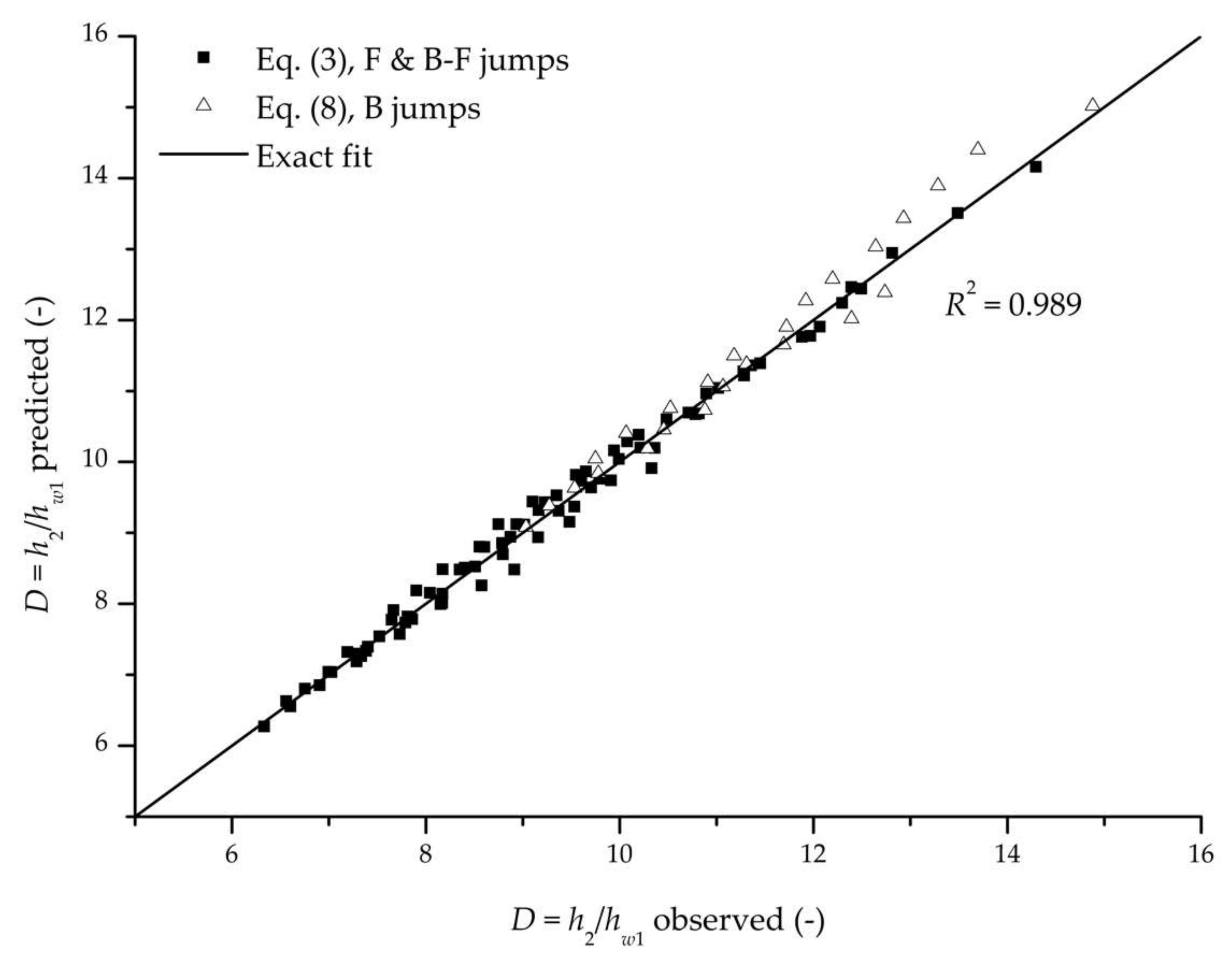
Equations (3) and (8) were found to be accurate in estimating the sequent depth ratios for B, F, and B-F jumps with R2 = 0.989 for the entire dataset (Figure 8), when Lr was obtained through Equation (9). The normalized RMSE value for Equation (3) was determined to be 2.41%. It was found that the impact of the strongly aerated incoming flow on the body of the hydraulic jump increases air concentrations in the roller when compared to the smooth chutes. The increased amount of the entrained air is likely to create a different pressure distribution on the apron. Unlike in ogee spillway design, a curved transition from the chute to the basin is omitted in stepped chutes, which can also lead to different pressure distribution. Therefore, it was important to compare the experimental data from our setup with the existing methods for smooth chutes.
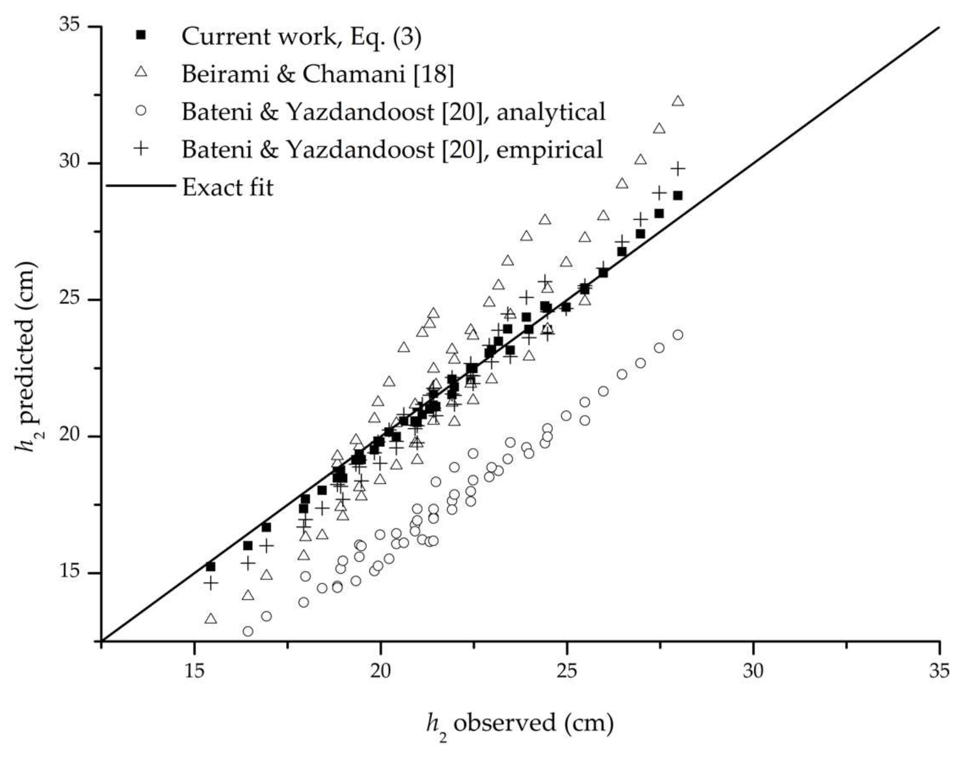
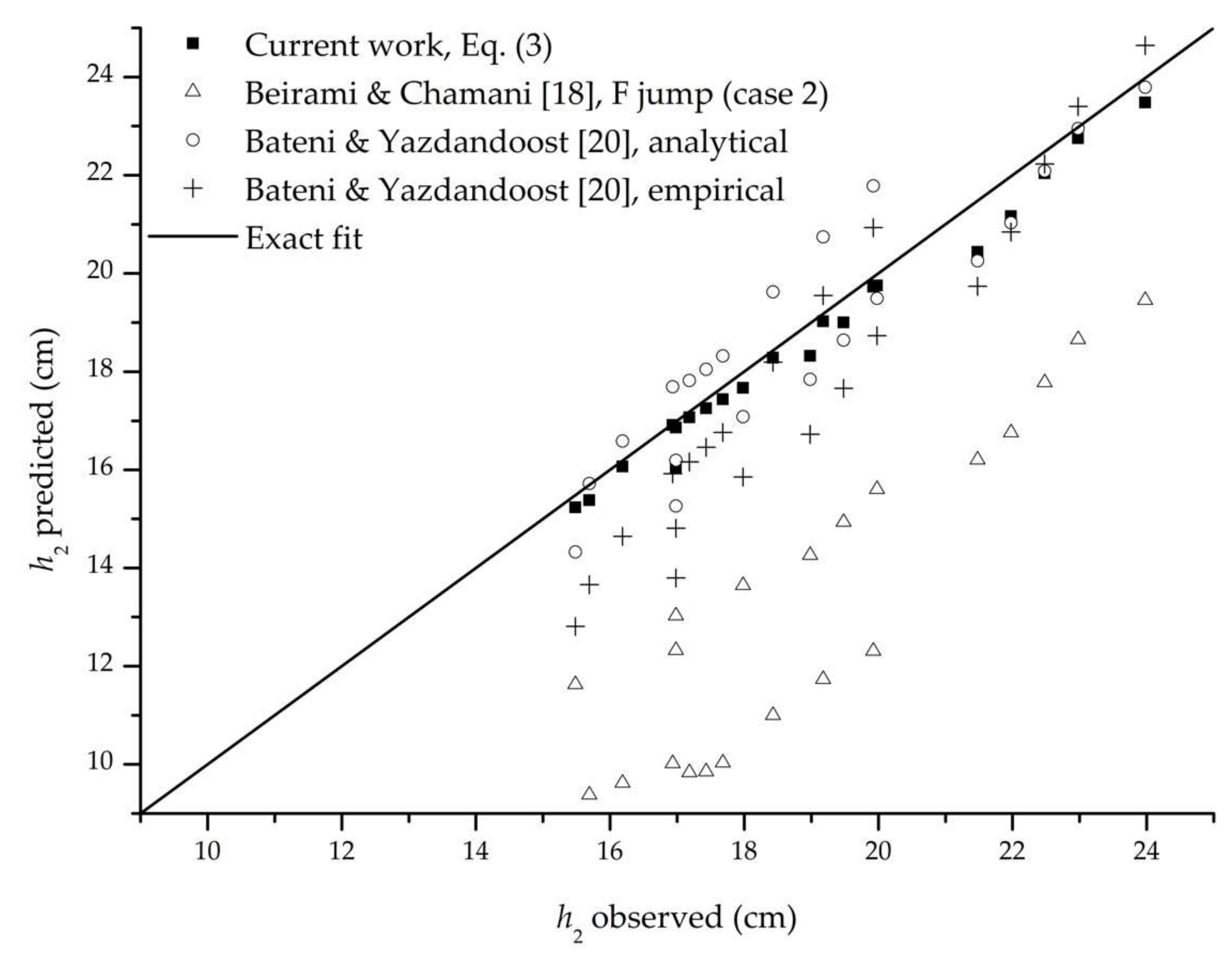
For comparison with the methods proposed by [18] for F and B-F jumps, the radius of the curvature at the end of the chute had to be estimated. We varied the value of the curve radius and found that the value of 9 cm gives the best agreement with experimental data. However, the conclusion about the hypothetical curve radius is problem specific and cannot be generalized. It was found for B-F jumps that method by [20] underestimates D for low values of hw1, and overestimates D for high values of hw1 (Figure 9), i.e., the method tends to underestimate D with the increase of F1. For F jumps, their method underestimates D for all tests by 30% on average and fails to account for different hydraulic jump positions along the chute. This confirms that adverse-slope basins perform differently with stepped chutes when compared to the smooth ogee chutes.
Figure 9 shows that the analytical method proposed by [20] for B-F jumps underestimates the sequent depth ratios for all tests by 20% on average. On the other hand, Figure 10 shows that their method for F jumps is in good agreement with our data and follows the trend of the observed depth h2. Figure 9 also shows that the empirical method proposed by [20] for B-F jumps is in better agreement with our data than their analytical method and follows the trend of observed depth h2, with symmetrical scatter of results. For F jumps, the empirical method follows the trend of observed depths h2 but mostly underestimates the observed values (Figure 10).
3.3. Hydraulic Efficiency
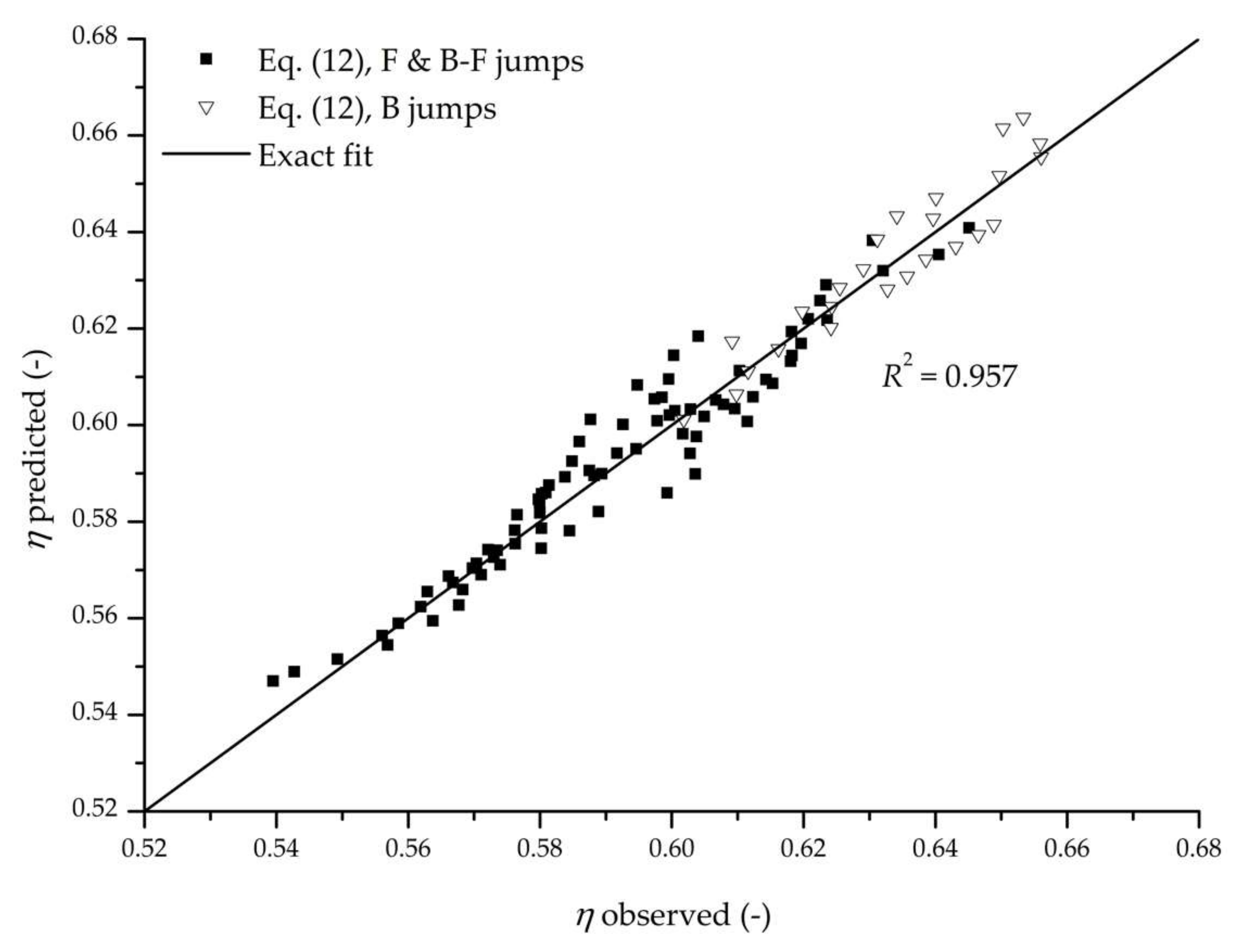
Using the Equations (3) and (9) it is possible to estimate the energy dissipation efficiency for B, F, and B-F jumps. During the preliminary stages of the design process, it is useful to have a simple relation for estimating the energy head loss for such hydraulic jump configurations. Based on the estimated incoming clear-water depths, hw1, and the measured downstream depths, h2, the energy dissipation coefficient, η, defined by Equation (6), was fitted to an empirical expression (R2 = 0.957 for the entire dataset, and NRMSE = 4.96%):
where b = 0.028(tan θ)−0.09 for F and B-F jumps, and b = 0.0395 for B jumps. Figure 12 shows the observed and predicted values of η. Results in Figure 12 display better agreement of Equation (12) for B jump than for F and B-F jumps. The reason for this may be due to the larger number of parameters for F and B-F jumps.
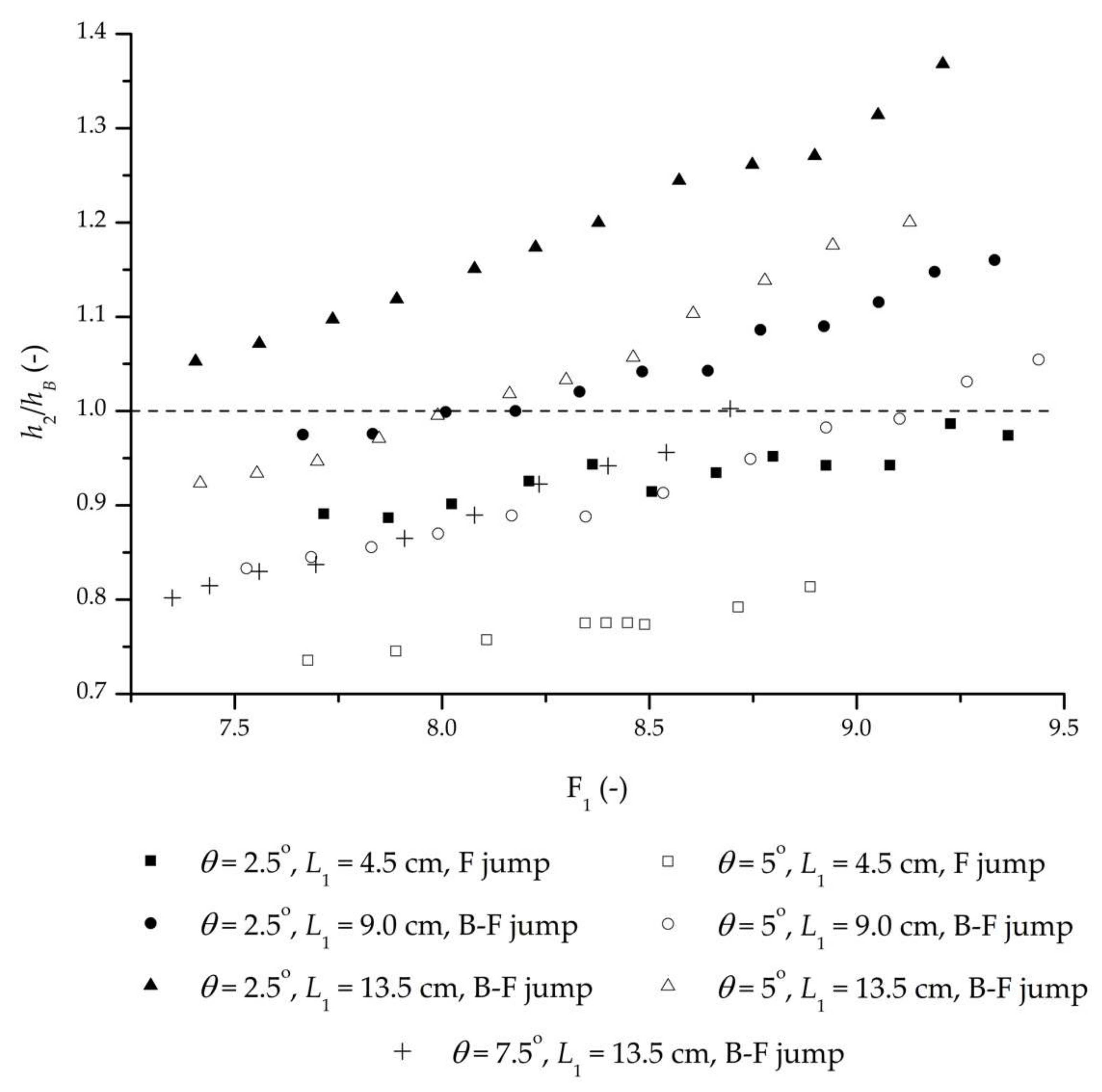
The advantages of sloped apron hydraulic jumps must also be assessed by comparing h2 with hB for the equivalent classical hydraulic jump on a flat bed. For configurations with h2/hB < 1, sloped apron stilling basins reduce the downstream sequent depth, and they can be used instead of classical stilling basins. Figure 13 shows the decrease of h2/hB with the decrease in F1, i.e., with the increasing discharge. This can be explained by the increase of the incoming flow force exerted on the apron, which in turn increases the apron reaction force. Figure 13 shows that the slope of h2/hB = f(F1) has a low dependency on θ but is strongly dependent on L1. Ratio h2/hB decreases with decreasing L1, which agrees with the findings by [7,8,18]. The minimum value of h2/hB (0.736) was obtained for θ = 5°, L1 = 4.5 cm and Q = 51.9 L/s, while the maximum (1.368) was obtained for θ = 2.5°, L1 = 13.5 cm and Q = 20.5 L/s. For θ = 7.5°, the hydraulic jump could not be established with L1 < 13.5 cm due to the length of the apron, which limited the minimum values of z2 (the tailwater level). All B jump configurations had h2/hB values higher than 1, since the transformation of the classical hydraulic jump to B jump requires an increase in tailwater level z2 (i.e., moving Section 1 in the upstream direction).
4. Conclusions
Based on the experimental and analytical work presented in this paper, the following conclusions can be drawn:
- Currently available methods for F and B-F jumps for smooth ogee spillways offer inconsistent results when applied to stepped-chute basins. Some existing methods for the estimation of hydraulic jump characteristics use parameters that cannot be defined for stepped chutes, which limits their applicability for such configurations. Unsatisfactory results of certain methods testify that stepped chutes exhibit different behavior than smooth ogee chutes.
- The method presented in this paper can be used to adequately estimate the characteristics of F and B-F jumps for adverse-slope basins of the stepped chutes. In addition to its performance for F and B-F jumps, the presented method also provides accurate results for B jumps in horizontal basins. This enables the investigation of a wide range of apron slopes with a single method, which was largely neglected in previous research.
- The sequent depths obtained through existing methods were found to vary greatly depending on the method used. For F jumps, sequent depths obtained using the analytical method provided by [20] were found to adequately describe the observed values, with relative errors between −8.9% to +8.9%. According to our method, relative errors were between −4.9% to +0.5%.
- For the estimation of sequent depth for B-F jumps it was determined that the empirical method by [20] provides good results, with relative errors ranging from −8.7% to 5.0% compared to our experimental data. With our method, the relative errors were between −2.1% to +4.2%.
- The roller lengths for B, F, and B-F jumps were estimated through several existing methods and it was found that the empirical expression given by [20] provides good results, with the relative error between −19.4% to 14.5% relative to our experimental data. However, the relative errors of our method were significantly smaller, ranging from −4.8% to +6.1%.
- Design of sloped stilling basins should consider both η and the ratio h2/hB. Only values of h2/hB < 1 reduce the necessary tailwater level for hydraulic jump stabilization. For values of h2/hB > 1, additional structural elements should be considered for energy dissipation.
The proposed approach for estimating the characteristics of the F, B-F, and B jumps for stepped spillways should be further tested with experimental data from both larger scale models and by using different spillway step heights, to alleviate the scale effects of the experimental setup. Furthermore, additional spillway chute angles should be examined to fully understand their effect on the stability and character of adverse-slope hydraulic jumps for stepped chutes. This can then be used to develop a general form of the proposed expressions. Additional data concerning the velocity and air concentration profiles is required to fully describe the differences between such hydraulic jumps for smooth and stepped chutes.
Future research should also focus on the relation between the incoming Froude number F1 and the impact of the velocity distribution on the general behavior of adverse-slope hydraulic jumps. This then focuses on the dominant component of Equation (3) for Section 1, which is the momentum of the flow (ρqv1β1 cos θ).
The addition of the energy dissipation elements should be another research focus, as they can provide significant improvements of the adverse-slope basin design, primarily the reduction of the basin length. Finally, a thorough investigation of the pressure distribution on the apron is necessary for the development of a general expression for the intensity of the apron reaction force.
Acknowledgments
This work was supported by the Ministry of Education, Science and Technological Development of Serbia (grants TR37009 and TR37010).
Author Contributions
All authors contributed to the design and development of this manuscript. Robert Ljubičić and Dragutin Pavlović conducted all experimental measurements (except EC measurements). Robert Ljubičić and Budo Zindović carried out the data analysis (except EC probe data) and were the authors of the original draft of the manuscript. Predrag Vojt and Dragutin Pavlović carried out EC probe measurements and subsequent analysis of the acquired data while also contributing many ideas to the study. Radomir Kapor and Ljubodrag Savić revised all versions of the paper and edited the manuscript prior to the submission. All authors read and approved the final manuscript. The authors would like to express their sincere gratitude to Dragan Savić at University of Exeter for his significant contribution in the final preparation of the manuscript.
Conflicts of Interest
The authors declare no conflict of interest.
Appendix A. Derivation of Expressions for Sequent Depth Ratio
Using the notation from Figure 1, a momentum Equation (1) can be rewritten as:
By dividing the Equation (A1) with , and substituting q = Q/B, it can be obtained:
Using mass conservation law for Section 1 and Section 2, the righthand side of the Equation (A2) can be transformed:
Finally, the Equation (3) in Section 2 is obtained from Equations (A2) and (A3) by introducing a set of dimensionless variables: D = h2/hw1, C = cos θ/cos φ, D1 = z1b/(hw1 cos φ), D2 = z2/(hw1 cos φ), DL = L/(hw1 cos φ), D2* = z2*/(hw1 cos φ), and F1 = v1/(g hw1 cos φ)0.5.
For B jumps, cos θ = 1, so the Equation (3) transforms into Equation (8), where C’ = 1/cos φ.
References
- Boes, R.; Hager, W.H. Two-phase flow characteristics of stepped spillways. J. Hydraul. Eng. 2003, 129, 661–670. [Google Scholar] [CrossRef]
- Boes, R.; Hager, W.H. Hydraulic design of stepped spillways. J. Hydraul. Eng. 2003, 129, 671–679. [Google Scholar] [CrossRef]
- Kindsvater, C.E. The hydraulic jump in sloping channels. Trans. Am. Soc. Civ. Eng. 1944, 109, 1107–1120. [Google Scholar]
- Bradley, J.N.; Peterka, A.J. Hydraulic design of stilling basins: Hydraulic jumps on a horizontal apron (Basin I). J. Hydraul. Div. 1957, 83, 1–24. [Google Scholar]
- Rajaratnam, N. Hydraulic jumps in sloping channels. J. Cent. Board Irrig. Pow. 1966, 23, 137–149. [Google Scholar]
- Rajaratnam, N.; Murahari, V. Flow characteristics of sloping channel jumps. J. Hydraul. Div. 1974, 100, 731–740. [Google Scholar]
- Hager, W.H. B-jump in sloping channel. J. Hydraul. Res. 1988, 26, 539–558. [Google Scholar] [CrossRef]
- Kawagoshi, N.; Hager, W.H. B-jump in sloping channel, II. J. Hydraul. Res. 1990, 28, 461–480. [Google Scholar] [CrossRef]
- Ohtsu, I.; Yasuda, Y. Hydraulic jump in sloping channels. J. Hydraul. Eng. 1991, 117, 905–921. [Google Scholar] [CrossRef]
- Adam, A.M.; Ruff, J.F.; AlQaser, G.; Abt, S.R. Characteristics of B-jump with different toe locations. J. Hydraul. Eng. 1993, 119, 938–948. [Google Scholar] [CrossRef]
- Carollo, F.G.; Ferro, V.; Pampalone, V. Sequent depth ratio of a B-jump. J. Hydraul. Eng. 2011, 137, 651–658. [Google Scholar] [CrossRef]
- Bejestan, M.S.; Shokrian, M. Mathematical expression for the B-jump sequent depth ratio on sloping bed. KSCE J. Civ. Eng. 2015, 19, 790–795. [Google Scholar] [CrossRef]
- Montano, L.; Felder, S. Air-water flow properties in hydraulic jumps on a positive slope. In Proceedings of the 37th IAHR World Congress, Kuala Lumpur, Malaysia, 13–18 August 2017. [Google Scholar]
- Rouse, H. Fluid Mechanics for Civil Engineers; McGraw-Hill: New York, NY, USA, 1938. [Google Scholar]
- Defina, A.; Susin, F.M.; Viero, D.P. Bed friction effects on the stability of a stationary hydraulic jump in a rectangular upward sloping channel. Phys. Fluids 2008, 20, 1–7. [Google Scholar] [CrossRef]
- McCorquodale, J.A.; Mohamed, M.S. Hydraulic jumps on adverse slopes. J. Hydraul. Res. 1994, 32, 119–130. [Google Scholar] [CrossRef]
- Hussain, D.; Alhamid, A.A.; Negm, A.M. Length and depth of hydraulic jump in sloping channels. J. Hydraul. Res. 1994, 32, 899–910. [Google Scholar] [CrossRef]
- Beirami, M.K.; Chamani, M.R. Hydraulic jumps in sloping channels: Sequent depth ratio. J. Hydraul. Eng. 2006, 132, 1061–1068. [Google Scholar] [CrossRef]
- Beirami, M.K.; Chamani, M.R. Hydraulic jump in sloping channels: Roller length and energy loss. Can. J. Hydraul. Eng. 2010, 37, 535–543. [Google Scholar] [CrossRef]
- Bateni, S.M.; Yazdandoost, F. Hydraulics of B-F and F jumps in adverse-slope stilling basins. Water Manag. 2009, 162, 321–327. [Google Scholar] [CrossRef]
- Chanson, H. Development of the Bélanger Equation and Backwater Equation by Jean-Baptiste Bélanger (1828). J. Hydraul. Eng. 2009, 135, 159–163. [Google Scholar] [CrossRef]
- Ohtsu, I.; Yasuda, Y.; Takahashi, M. Flow characteristics of skimming flow in stepped channels. J. Hydraul. Eng. 2004, 130, 860–869. [Google Scholar] [CrossRef]
- Toombes, L. Experimental Study of Air–Water Flow Properties on Low-Gradient Stepped Cascades. Ph.D. Thesis, University of Queensland, Brisbane, Australia, 2002. [Google Scholar]
- González, C. An Experimental Study of Free-Surface Aeration on Embankment Stepped Chutes. Ph.D. Thesis, University of Queensland, Brisbane, Australia, 2005. [Google Scholar]
- Zindovic, B.; Vojt, P.; Kapor, R.; Savic, L.S. Converging stepped spillway flow. J. Hydraul. Res. 2016, 54, 699–707. [Google Scholar] [CrossRef]
Figure 1.
Adverse-slope hydraulic jump (B-F type) for stepped spillways with presumed pressure distributions.
Figure 1.
Adverse-slope hydraulic jump (B-F type) for stepped spillways with presumed pressure distributions.

Figure 2.
Experimental setup.

Figure 3.
Observed vs. predicted roller length, relative to hw1.

Figure 4.
Observed vs. predicted roller lengths for F and B-F type jumps.

Figure 5.
Comparison of two proposed expressions for estimating the roller length.

Figure 6.
Observed vs. predicted roller lengths, relative to h2.

Figure 7.
Relative velocity profiles at Section 1 for L1 = 13.5 cm, where vm is the maximum profile velocity.
Figure 7.
Relative velocity profiles at Section 1 for L1 = 13.5 cm, where vm is the maximum profile velocity.

Figure 8.
Observed vs. predicted sequent depth ratios.

Figure 9.
Comparison of different methods for predicting downstream depth h2 for B-F jumps.

Figure 10.
Comparison of different methods for predicting downstream depth h2 for F jumps.

Figure 11.
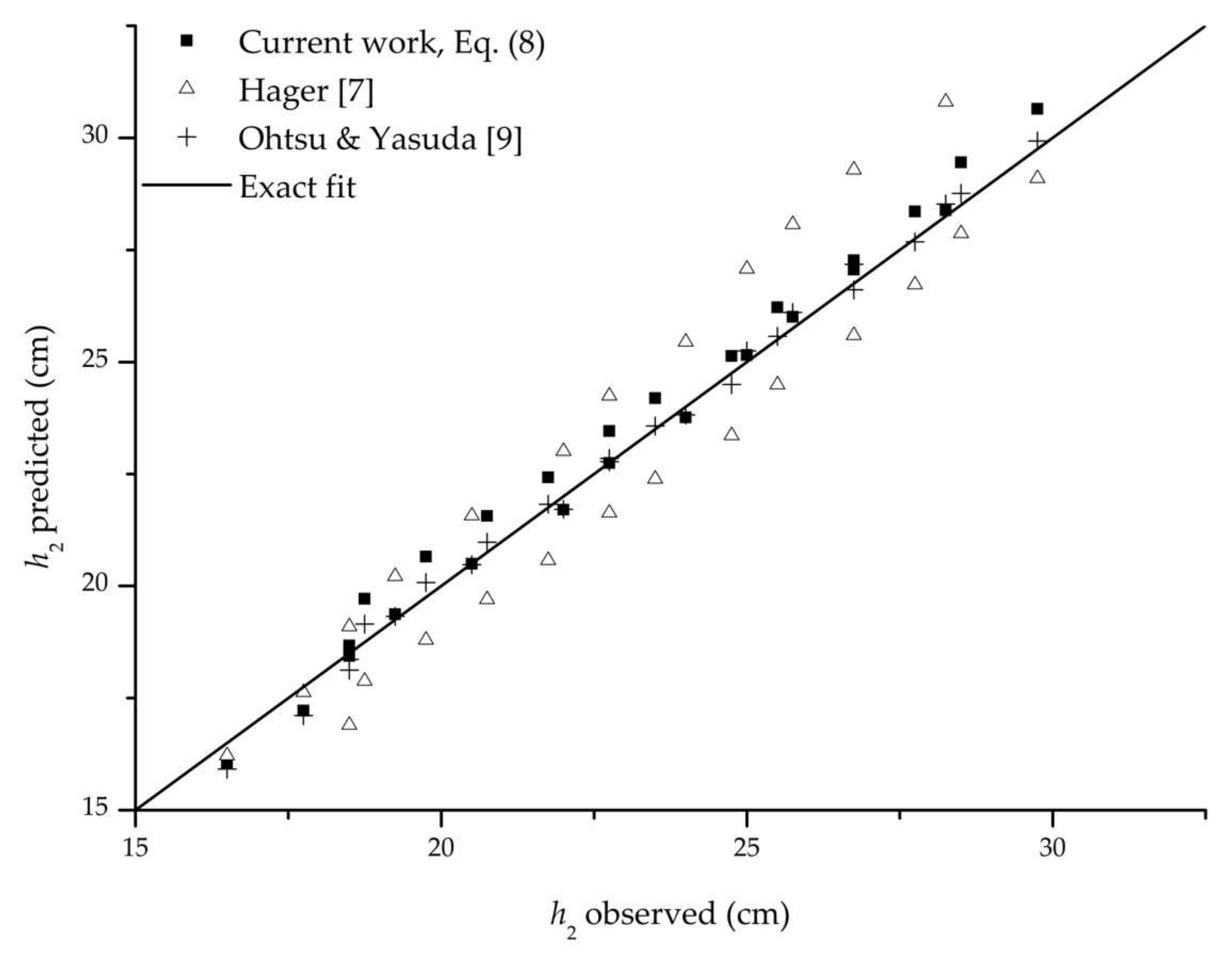
Comparison of different methods for predicting downstream depth h2 for B jumps.

Figure 12.
Observed vs. predicted energy dissipation coefficient.

Figure 13.
Comparison of h2/hB for different configurations of F and B-F jumps.


Table 1.
Summary of results for different methods for estimation of sequent depth h2.
| Method | B Jump | F Jump | B-F Jump |
|---|---|---|---|
| Bateni & Yazdandoost (2009) analytical | - | R2 = 0.867, NRMSE = 11.00% | R2 = 0.960, NRMSE = 34.09% |
| Bateni & Yazdandoost (2009) empirical | - | R2 = 0.931, NRMSE = 18.71% | R2 = 0.978, NRMSE = 6.35% |
| Beirami & Chamani (2006) | - | R2 = 0.803, NRMSE = 29.43% | R2 = 0.899, NRMSE = 14.71% |
| Hager (1988) | R2 = 0.898, NRMSE = 10.23% | - | - |
| Ohtsu & Yasuda (1991) | R2 = 0.996, NRMSE = 2.14% | - | - |
| Current work, Lr estimated by Equation (9) | R2 = 0.989, NRMSE = 4.19% | R2 = 0.991, NRMSE = 5.37% | R2 = 0.993, NRMSE = 2.93% |
| R2 = 0.990, NRMSE = 3.08% | |||
Table 2.
Summary of results for different methods for estimation of roller length Lr.
| Method | B Jump | F Jump | B-F Jump |
|---|---|---|---|
| Bateni & Yazdandoost (2009) | - | R2 = 0.795, NRMSE = 10.88% | |
| - | |||
| Beirami & Chamani (2010) | - | R2 = 0.614, NRMSE = 14.70% | |
| McCorquodale & Mohamed (1994) | - | R2 = 0.636, NRMSE = 28.66% | |
| Current work, Lr estimated by Equation (9) | R2 = 0.983, NRMSE = 3.15% | ||
© 2018 by the authors. Licensee MDPI, Basel, Switzerland. This article is an open access article distributed under the terms and conditions of the Creative Commons Attribution (CC BY) license (http://creativecommons.org/licenses/by/4.0/).
Share and Cite
MDPI and ACS Style
Ljubičić, R.; Zindović, B.; Vojt, P.; Pavlović, D.; Kapor, R.; Savić, L. Hydraulic Jumps in Adverse-Slope Stilling Basins for Stepped Spillways. Water 2018, 10, 460. https://doi.org/10.3390/w10040460
AMA Style
Ljubičić R, Zindović B, Vojt P, Pavlović D, Kapor R, Savić L. Hydraulic Jumps in Adverse-Slope Stilling Basins for Stepped Spillways. Water. 2018; 10(4):460. https://doi.org/10.3390/w10040460
Chicago/Turabian StyleLjubičić, Robert, Budo Zindović, Predrag Vojt, Dragutin Pavlović, Radomir Kapor, and Ljubodrag Savić. 2018. "Hydraulic Jumps in Adverse-Slope Stilling Basins for Stepped Spillways" Water 10, no. 4: 460. https://doi.org/10.3390/w10040460
Note that from the first issue of 2016, this journal uses article numbers instead of page numbers. See further details here.